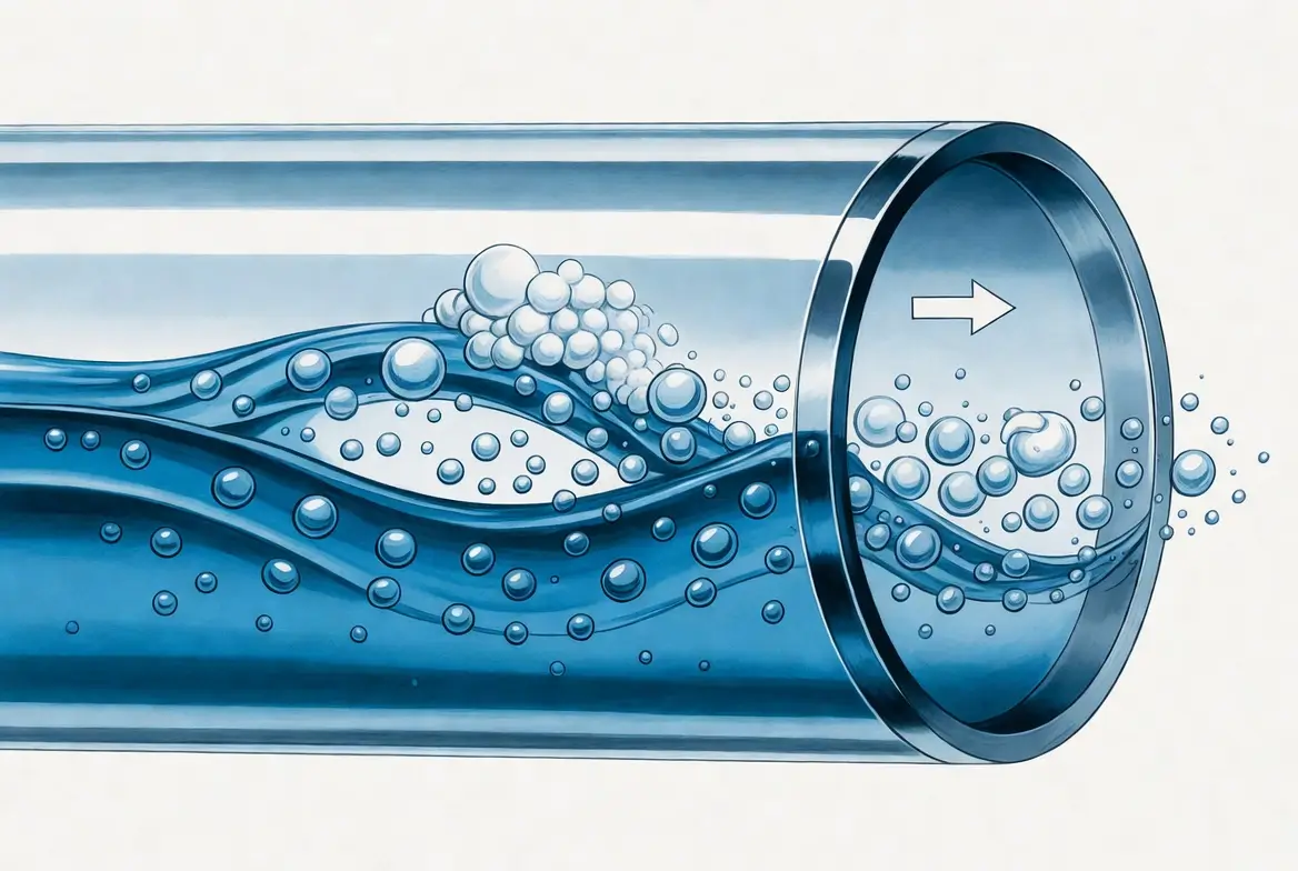
Understanding how fluids behave inside piping is one of the most important skills for process and mechanical engineers working in chemical plants. While fluid mechanics can appear complicated, many real-world piping problems can be understood from one simple principle:
Gas rises. Liquid settles.
Once this basic concept becomes intuitive, many common engineering topics—including condensate accumulation, gas-liquid separation, piping layout, pump startup, and utility system design—become much easier to understand.
This article introduces eight practical examples that help engineers visualize what is actually happening inside industrial piping.
- 1. Gas Rises, Liquid Falls
- 2. Liquids Accumulate at Low Points
- 3. Why Nitrogen Blow Does Not Remove Everything
- 4. Flow Control Sometimes Requires Intentional Liquid Hold-Up
- 5. Separating Oil from Water
- 6. Separating Gas from Liquid
- 7. Steam Condensation Inside Pipes
- 8. Pump Startup and Air Entrapment
- Why This Mental Model Matters
- Conclusion
- About the Author – NEONEEET
1. Gas Rises, Liquid Falls
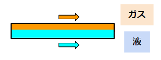
At atmospheric conditions, gases are much less dense than liquids. Consequently, when gas and liquid flow together inside a horizontal pipe, gravity naturally separates them.
The gas occupies the upper portion of the pipe, while the liquid flows along the bottom.
Although two-phase flow can become extremely complex depending on velocity and flow regime, remembering this basic picture provides an excellent starting point for engineering judgment.
2. Liquids Accumulate at Low Points
Because liquids settle downward, they naturally collect in low sections of piping.
One common example is the U-seal, where water intentionally remains inside the bend to isolate process gas from the atmosphere.
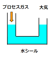
These seals improve safety, but accumulated liquid must still be maintained because dissolved process chemicals and floating contaminants gradually reduce sealing performance.
Recognizing where liquid naturally accumulates is an essential part of piping design.
3. Why Nitrogen Blow Does Not Remove Everything
Nitrogen purging is frequently used to remove residual liquid from pipelines.
However, engineers often assume that nitrogen can completely push all liquid out of the pipe.
In reality, once nitrogen creates a flow path through the upper portion of the pipe, the gas simply bypasses much of the remaining liquid because gas naturally occupies the upper region while liquid remains trapped below.
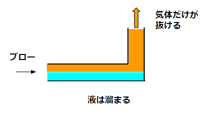
Repeating the purge several times reduces the remaining liquid but rarely eliminates it entirely.
Understanding gas-liquid behavior prevents unrealistic expectations during plant operation.
4. Flow Control Sometimes Requires Intentional Liquid Hold-Up
Certain flowmeters require the measurement section to remain completely filled with liquid.
To achieve this, piping is sometimes intentionally designed with a small liquid pocket or U-shaped section.
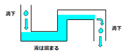
Although engineers usually try to eliminate liquid accumulation, there are situations where deliberately retaining liquid actually improves measurement accuracy and process control.
5. Separating Oil from Water
The same density principle also explains gravity separation.
Since oil is lighter than water, oil naturally floats while water settles.
Many oil-water separators simply provide enough residence time for gravity to perform the separation before each phase exits through different outlets.
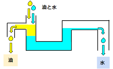
This is one of the simplest and most reliable separation methods used throughout chemical plants.
6. Separating Gas from Liquid
Gas-liquid separators also rely on the same physical principle.
When horizontal flow enters a vessel or pipe section, gas tends to migrate upward while liquid moves downward.
Proper branch connections placed at the top and bottom allow each phase to exit independently.
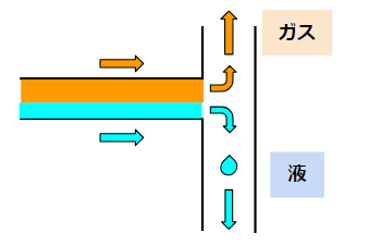
This concept is applied in knockout drums, separator vessels, condensate pots, and numerous troubleshooting situations encountered during plant operation.
7. Steam Condensation Inside Pipes
Steam condensation offers another useful example.
As steam contacts a cooler pipe wall, condensation begins at the surface first.
A thin liquid film develops on the wall while vapor continues flowing through the center of the pipe.
Eventually, both condensate and vapor travel together as a two-phase flow before complete condensation occurs.
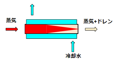
Although most heat exchanger calculations focus only on heat-transfer area, visualizing this physical process helps engineers better understand what actually happens inside the equipment.
8. Pump Startup and Air Entrapment
Successful pump startup depends on the pump casing being completely filled with liquid.
Air trapped inside the casing prevents proper priming and may stop the pump from developing flow.
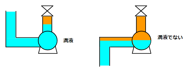
Self-priming pumps solve this problem by intentionally retaining liquid inside the pump body.
Rather than being a complicated mechanism, self-priming technology is fundamentally based on controlled liquid retention.
Understanding where gas naturally accumulates explains why these pumps work.
Why This Mental Model Matters
Many piping layouts, operating procedures, and troubleshooting methods become much easier once engineers stop memorizing equipment and begin visualizing fluid behavior.
Instead of asking which component should be installed, experienced engineers often begin by asking:
“Where will the gas go?”
“Where will the liquid collect?”
Answering those two questions correctly often leads to the correct engineering solution.
Conclusion
Fluid flow inside industrial piping does not have to be mysterious.
In many cases, the first step toward understanding complex process behavior is simply recognizing that gas naturally rises while liquid naturally settles.
From condensate management and nitrogen purging to separator design and pump startup, this basic physical principle explains countless situations encountered in chemical plants.
Once engineers develop the habit of mentally visualizing where each phase will move, piping systems become significantly easier to design, operate, and troubleshoot.
About the Author – NEONEEET
A user‑side chemical plant engineer with 20+ years of end‑to‑end experience across design → production → maintenance → corporate planning. Sharing practical, experience‑based knowledge from real batch‑plant operations. → View full profile



Comments