Reading P&IDs (Piping & Instrumentation Diagrams) is a fundamental skill for plant designers, operators and maintenance staff. But P&IDs can look like a jungle of shapes and lines at first glance — tanks, pumps, heat exchangers, valves, strainers… which symbol means what, and how does that affect design or operation?
This guide translates the common P&ID symbols used in batch chemical plants into plain engineering terms. You’ll learn how to identify key equipment, piping items and valves on a drawing, and — more importantly — how those symbols reflect real-world installation and operating constraints.
How to Read P&ID Diagrams in Batch Chemical Plants – A Beginner’s Guide
Beginner’s Guide to P&ID Instrument Symbols – What Do Those Letters and Circles Mean?
What You Can Learn from P&ID Line Specifications in Chemical Plants
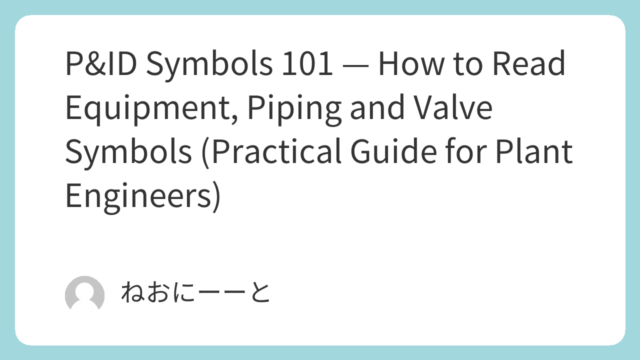
Equipment symbols — tanks, vessels and towers
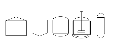
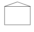
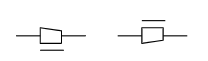
- Tank (storage): usually shown as a simple cylinder. Variants include flat top, cone-roof (venting) and cone-bottom / hopper (for solids).
- Pressurised vessel: thicker lines or extra marks indicate a pressure-rated tank (reinforced shell). In batch plants, these are often used for vacuum/low-pressure services as well.
- Agitated/Reacting vessel (stirred tank): tank symbol with an agitator shaft or motor mark. Expect jackets for heating/cooling and manways shown nearby.
- Tower / column: tall rectangle or cylinder with internals often omitted on small P&IDs — recognize by top/bottom nozzle arrangements.
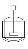
Practical tip: equipment symbols tell you expected access, maintenance needs and whether jackets/insulation are required — don’t treat them as decorative.
Pump symbols — common pump types
- Centrifugal (volute) pump: circle + triangular inlet/outlet; typical for most liquid transfer.
- Vertical pumps / canned / mag drive: variants indicate orientation and sealless types — useful for seal/containment planning.
- Vacuum pumps / ejectors: special shapes indicating water-sealed or steam/air ejectors. These implicate drains, vents and condenser requirements.
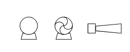
Practical tip: note pump seal symbol (mechanical seal vs gland) — affects piping for flush plans and seal support systems.
Heat exchanger symbols
- Shell-and-tube: classic symbol (cylinder with internal tube indication). Most common in batch plants.
- Plate heat exchanger: usually a rectangle with parallel lines. Compact but requires plate maintenance space.
- Spiral / block: less common; symbol and notes should indicate expected fouling characteristics.
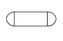
Practical tip: the exchanger symbol plus inlet/outlet nozzle positions indicate which side is shell/tube — important for tracer tests and maintenance routing.
Valve symbols — what to look for and why it matters
Valves are the language of P&IDs. Small differences matter.
- Gate valve: basic isolation — typically drawn as two triangles facing each other. Good for on/off service.
- Globe valve: shown as a filled symbol — used for throttling/control and requires actuators for remote control.
- Ball valve: circle in the valve body — common for quick on/off and often used as manual isolation.
- Butterfly valve: disc symbol — space-and-torque considerations matter for large diameters.
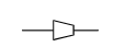
- Check valve (non-return): small triangle + stop — note direction! Different types (lift, swing, ball, spring) have different installation constraints and performance.
- Diaphragm valve: curved line representing the membrane — popular for slurry/abrasive services.
- Safety relief / pressure-reducing valves: spring symbol often shown; pay attention to discharge routing.


Practical tip: valve actuation (manual, pneumatic, electric) is indicated by an actuator symbol. That determines instrument air or power needs and location of control cabinets.
Piping accessories and items often overlooked
- Reducers (concentric / eccentric): show flow orientation — eccentric reducers are used where liquid drainage is critical.
- Strainers / filters: symbol usually an S in a box or Y shape — maintenance access and bypass lines should be considered.
- Steam traps, vents, flash valves: small symbols but critical for heat tracing and condensate handling.
- Flexible hoses / expansion joints: shown as corrugated rectangles or special markers — plan routing to avoid vibration failures.
- Flame arrestors (frame arrestors): appear similar to other inline items — ensure correct placement on vapor lines.


Legend, standards and company rules
P&IDs should include a legend (LEGEND). While JIS, ISO and ANSI provide symbol standards, many companies use tailored sets. Always rely on the diagram’s legend and the line spec sheet when in doubt.
Practical tip: if a symbol is ambiguous on the drawing, check the line spec (material, insulation, design pressure/temperature) — it usually clarifies duty, material and valve type.
Summary / Key takeaways
- Learn the handful of symbols you see most often first (tanks, pumps, shell-tube exchangers, gate/ball/check valves).
- Symbols carry operational meaning: installation direction, maintenance access, and piping specifics (drains, vents, bypasses).
- Always cross-reference the P&ID with the legend, line spec and equipment datasheets — symbols are shorthand, not the whole story.
- For batch plants: expect many shell-and-tube exchangers, stirred tanks with jackets, and a mix of manual and automated valves — design and maintain with service changeover in mind.
About the Author – NEONEEET
A user‑side chemical plant engineer with 20+ years of end‑to‑end experience across design → production → maintenance → corporate planning. Sharing practical, experience‑based knowledge from real batch‑plant operations. → View full profile
Comments