In chemical and process plants, the mixing power of an agitated tank or reactor is a key factor for achieving proper mixing performance and energy efficiency.
However, the actual power calculation often feels too theoretical — especially for on-site engineers who just need a practical way to estimate the required power.
This article explains the basic equations behind mixing power in a simplified and intuitive way.
By understanding these fundamentals, you’ll be able to:
- Estimate the required motor power on-site
- Understand how impeller size and speed affect mixing energy
- Improve design efficiency and reduce power losses
Let’s explore how mixing power is structured, calculated, and connected to both mechanical and electrical aspects of your agitator system.
Agitator Design Basics: Understanding Power per Unit Volume (Pv) and Motor Power
Beginner’s Guide to Agitator Shaft Strength Calculation
What Is Critical Speed in Agitators? Resonance Principles and Practical Calculations
1. The Structure of Mixing Power
When we talk about the “required mixing power,” two parts are involved:
- Mechanical side – the impeller’s motion in the liquid
- Electrical side – the motor and transmission delivering that power
Many engineers focus on the mechanical calculation (like in pump head-loss analysis) but overlook the electrical losses that occur before power reaches the shaft.
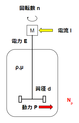
From an energy-flow perspective, it’s easier to understand the system if we start from the mechanical power (fluid side) and then trace it back to the input electricity.
2. Reynolds Number in Mixing
The first step in power estimation is determining the Reynolds number (Re) for the system:
$$ Re=\frac{d^2Nρ}{μ} $$
Where:
- d = impeller diameter
- N = rotation speed
- ρ = liquid density
- μ = liquid viscosity
Reynolds number defines whether the flow is laminar, transitional, or turbulent.
It also directly affects the power number (Np), which you’ll need later.
For scale-up:
When increasing impeller diameter (d), the speed (N) must be reduced to keep Re constant — ensuring similar flow behavior.
3. Net Mixing Power (P)
The most basic expression for required mixing power is:
$$ P=N_pρN^3d^5 $$
Where:
- Np = power number (depends on impeller type and flow regime)
- ρ = liquid density
- N = rotational speed
- d = impeller diameter
This equation shows that mixing power increases with the cube of speed and the fifth power of impeller diameter.
Even a small change in d or N has a large impact — which is why careful scaling is essential.
4. Understanding the Power Number (Np)
The power number is an empirical factor that links flow pattern and impeller geometry to power consumption.
For example, the well-known Nagata correlation relates Np to the Reynolds number:
- At low Re, viscous effects dominate, and Np decreases rapidly with increasing Re.
- At high Re, flow becomes turbulent, and Np approaches a constant value.
Each impeller type (e.g., Rushton turbine, pitched-blade, propeller) has a characteristic Np–Re curve used in industrial design.
5. Why “Cubic and Quintic”?
You may wonder why the formula includes N³ and d⁵.
Let’s check the physical basis:
Power = Force × Velocity
The impeller’s force is proportional to the momentum change of the liquid: F∝ρ×(d2)×(Nd)2=ρN2d4F \propto \rho \times (d^2) \times (N d)^2 = \rho N^2 d^4F∝ρ×(d2)×(Nd)2=ρN2d4
Multiplying by the impeller tip velocity (Nd): P∝ρN3d5P \propto \rho N^3 d^5P∝ρN3d5
Thus, the exponents arise naturally from dimensional analysis and momentum balance — not just empirical fitting.
6. Power Losses in the System
The power calculated above is the net mixing power, not the total electrical input.
In reality, losses occur in the motor and gearbox:
$$ E=\frac{P}{η_1η_2} $$
Where:
- η₁ = motor efficiency
- η₂ = gear reducer efficiency
If η₁ = 0.9 and η₂ = 0.8, then:
$$ E=\frac{P}{0.72} =1.38P$$
So the electrical power required is about 38% higher than the theoretical mixing power.
Ignoring these losses can lead to undersized motors and reliability issues.
7. Relation Between Power and Current
Electrical power input can be expressed as: E=3 VIcosϕE = \sqrt{3} \, V I \cos\phiE=3VIcosϕ
Where:
- V = voltage
- I = current
- cosφ = power factor
Since voltage and power factor remain nearly constant, current is directly proportional to the mixing load.
When using an inverter to adjust agitator speed, observing current is an easy way to check the mechanical power trend.
Conclusion
This article covered the fundamental relationships in mixing power calculation — focusing on the practical equations that every process or mechanical engineer should understand:
| Concept | Formula | Purpose |
|---|---|---|
| Reynolds Number | $$ Re=\frac{d^2Nρ}{μ} $$ | Defines flow regime |
| Power Equation | $$ P=N_pρN^3d^5 $$ | Calculates net mixing power |
| System Loss | $$ E=\frac{P}{η_1η_2} $$ | Accounts for motor & gearbox losses |
About the Author – NEONEEET
A user‑side chemical plant engineer with 20+ years of end‑to‑end experience across design → production → maintenance → corporate planning. Sharing practical, experience‑based knowledge from real batch‑plant operations. → View full profile
Comments
thank you so much