In chemical plants, drain piping looks simple—but small design choices can create serious liquid hold-up problems.
Compared with food or pharmaceutical plants, chemical facilities have more relaxed sanitary requirements, but avoiding liquid accumulation is still crucial for safety, operability, product quality, and maintenance.
Drain lines can be arranged in several patterns, and if mechanical engineers don’t guide the piping designers properly, operators may end up dealing with unnecessary risks or operational difficulties.
This article explains the practical drain-line configurations used in chemical plants and highlights the common pitfalls that lead to unwanted liquid pockets.
- 1. Vertical Drain (Basic Configuration)
- 2. Horizontal Offset Drain
- 3. Fully Horizontal Drain
- 4. Draining Slurry or High-Viscosity Lines
- 5. Diaphragm Valves and Liquid Hold-Up
- 6. Ball Valves and Gate Valves: Hidden Liquid Pockets
- 7. Other Sources of Liquid Hold-Up (Often Overlooked)
- 8. Liquid Hold-Up Is About Acceptable Limits
- ✅ Conclusion(まとめ)
- About the Author – NEONEEET
1. Vertical Drain (Basic Configuration)
The most fundamental drain arrangement is the vertical drop.
In P&ID drawings, it appears very simple: a takeoff from the lowest point of the main line.
A vertical drain allows nearly complete removal of liquid because it taps the lowest elevation of the pipe.
Whenever possible, this is the preferred method.
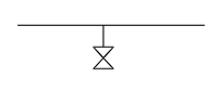
2. Horizontal Offset Drain
While vertical drains are ideal, they require vertical space.
In Japanese chemical plants—where tight equipment layouts are common—the elevation available around pumps and foundations may be insufficient.
Raising pump foundations increases cost, vibration risk, and sometimes even reactor height.
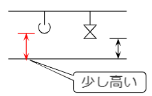
To gain extra elevation without structural changes, designers sometimes add a short horizontal offset before dropping vertically.
This helps secure a bit more height, but brings operability concerns:
- A bucket cannot sit directly under the drain.
- Operators must hold the bucket manually.
- A small slip can cause liquid splash accidents.
For these reasons, this method should be used sparingly.
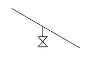
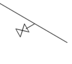
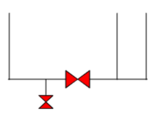
3. Fully Horizontal Drain
A development of the above is the horizontal drain, where the takeoff is made directly from the side of the pipe.
However, liquid drainage quality depends heavily on the fitting selection.
Avoid Reducing Tees
Example: draining a 2-inch main line using a 1-inch drain.
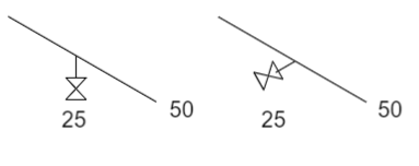
Using a reducing tee on a horizontal drain leaves un-drainable liquid because the branch connection sits above the pipe’s bottom.
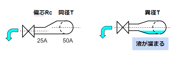
Instead, use:
- a full-size tee, then
- a concentric reducer to the smaller drain size.
This ensures complete drainage, but increases length and creates tripping hazards.
Still, it is the safer and more functional approach.
4. Draining Slurry or High-Viscosity Lines
For slurry services, horizontal drains are sometimes preferred.
Use:
- a full-size tee at the horizontal run
- matching the main line diameter
This helps redirect flow and reduces clogging risk—especially between tanks and pumps.
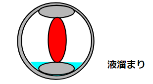
5. Diaphragm Valves and Liquid Hold-Up
Many engineers know that diaphragm valves should be installed horizontally—but few understand why.
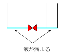
When Installed Upward
Upward-facing diaphragm valves always create a liquid pocket upstream and sometimes downstream.
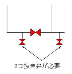
If both sides have no dedicated drain valves, the liquid remains trapped.
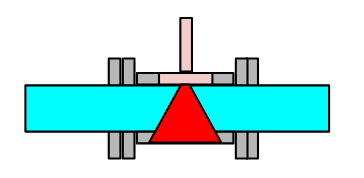
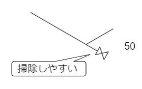
When Installed Horizontally
Horizontal installation minimizes hold-up, but does not eliminate it.
A small internal constriction (“the throttling section”) still traps some liquid.
Therefore:
- Always assume some residual liquid remains.
- Consider drain valves on either side if necessary.
- Treat the valve as a potential hazard during removal or maintenance.
6. Ball Valves and Gate Valves: Hidden Liquid Pockets
Ball valves have an internal cavity where liquid becomes trapped whenever the valve is cycled.
This is a known cause of liquid sealing, pressure buildup, and chemical accidents.
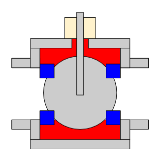
Gate valves have similar pocket areas.
Liquid cannot be fully drained from these valves; designers must account for this behavior in safety planning and maintenance procedures.
7. Other Sources of Liquid Hold-Up (Often Overlooked)
Leveling Tool Error
Piping slopes are installed based on bubble-level tools, which naturally introduce ± error.
Even a small deviation creates unintended low spots.
Gasket ID vs. Pipe ID Mismatch
Flange gaskets rarely match pipe IDs perfectly.
This small step creates a retention point.
Weld Root Beads
Welded joints produce internal beads.
Even stainless-steel welds have measurable irregularities.
Glass-lined or fluoropolymer-lined pipes are smoother but still have minor waviness.
Internal Surface Roughness
No industrial pipe has a perfectly smooth interior.
All have micro-pockets that retain some liquid.
8. Liquid Hold-Up Is About Acceptable Limits
Engineers cannot eliminate liquid hold-up entirely.
Instead, they must balance:
- product loss,
- thermal degradation,
- contamination between phases,
- operational risk.
Mechanical engineers tend to pursue “zero hold-up,” but production teams operate with acceptable thresholds.
Shared understanding between engineering and operations is essential.
✅ Conclusion(まとめ)
Drain-line design in chemical plants involves more than simply attaching a tap to a pipe.
Vertical drains offer the best performance, but horizontal solutions are sometimes necessary.
Diaphragm valves, ball valves, gaskets, welds, and even minor slope errors all contribute to liquid pockets.
Rather than aiming for zero hold-up, engineers should understand equipment characteristics, identify realistic risks, and design within acceptable limits.
This practical awareness helps protect operators—and yourself—from unintended hazards.
About the Author – NEONEEET
A user‑side chemical plant engineer with 20+ years of end‑to‑end experience across design → production → maintenance → corporate planning. Sharing practical, experience‑based knowledge from real batch‑plant operations. → View full profile
Comments