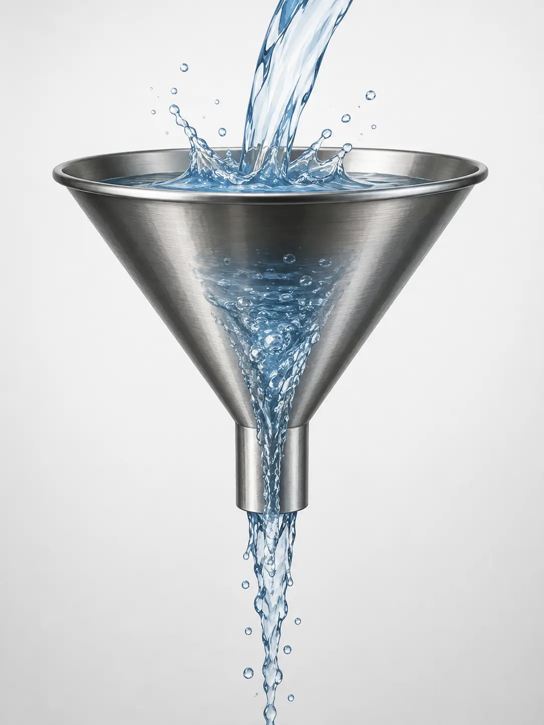
Drain funnels are simple-looking components, but they can create unexpected operational and safety problems when their size and connected piping are not properly designed.
In chemical plants, drain funnels are commonly used to receive liquids discharged from process and utility piping and direct them to a drain system. They are also found at the outlets of steam traps and other equipment where a liquid stream needs to be discharged to atmosphere.
The basic concept seems straightforward: receive the liquid and drain it away. However, if the discharge flow rate is higher than the capacity of the funnel and drain piping, liquid can splash or overflow from the funnel.
This can be particularly problematic when the discharged liquid is hot water, steam condensate, or another process fluid that presents a safety or environmental risk.
This article explains the basic design approach for drain funnels, focusing on the relationship between the process pipe, reducer, funnel, and drain line, as well as the differences between continuous and batch discharge.
What Is a Drain Funnel?
A drain funnel is essentially a funnel-shaped drain receiver used to collect liquid discharged from piping or equipment and direct it into a drain system.
In chemical plants, drain funnels are often used where a process or utility line is intentionally separated from the closed piping system and discharged to atmosphere before entering a floor drain or other drainage system.
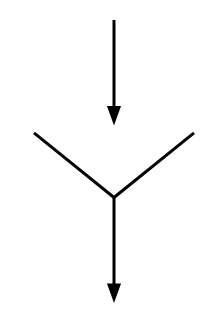
They can be used, for example, for:
- Steam trap discharge
- Condensate drainage
- Cooling-water discharge
- Equipment drain connections
- Utility piping drains
The basic concept is simple, but the funnel should not be treated as merely a piece of sheet metal or piping.
The entire system consisting of the process pipe, funnel/reducer, and drain pipe needs to be considered together.
Why Can Liquid Splash or Overflow from a Drain Funnel?
One of the most common problems with a drain funnel is liquid escaping from the funnel instead of flowing smoothly into the drain line.
This can happen even when the funnel itself appears sufficiently large.
For example, consider hot-water or steam-condensate discharge.
If the liquid enters the funnel at high velocity, the incoming liquid may splash against the funnel wall or accumulate faster than it can leave through the drain pipe.
The problem becomes more serious when the process piping is pressurized.
Once pressurized liquid is released to atmosphere, part of the pressure energy is converted into velocity. Therefore, simply looking at the nominal pipe size is not enough to determine whether the funnel will operate safely.
For hot water or steam condensate, liquid splashing around the funnel can create a burn hazard. In addition, water on the surrounding floor can create slip and fall risks.
Therefore, the drain funnel should be designed based on the actual discharge conditions rather than only its nominal size.
Basic Drain Funnel Sizing
A drain funnel system can be considered as three basic sections:
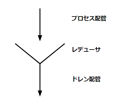
Process piping → Funnel/reducer → Drain piping
Each section has a different design consideration.
Process Piping
The process pipe is generally sized according to the process requirements.
In chemical plants, drain funnels are often associated with utility services rather than the main process stream. For example, cooling-water piping may be sized based on the required heat-transfer capacity of the equipment.
As an example, consider the following conditions:
- Pipe size: 50A
- Pressure: 200 kPa
- Material: SGP
If the water is being forced through the pipe by a pump and the velocity is approximately 2 m/s, the flow rate through a 50A pipe is roughly 240 L/min.
This flow rate is an important starting point for designing the downstream funnel and drain piping.
The key point is that the drain system must be able to handle the actual discharge flow rate of the process pipe.
Reducer and Funnel Size
The reducer section is where the process pipe connects to the larger funnel.
A basic minimum requirement is that the inside diameter of the funnel opening should be larger than the outside diameter of the incoming process pipe.
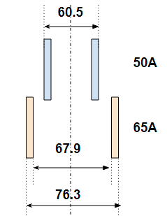
For example, a 50A SGP pipe has an outside diameter of approximately 60.5 mm.
A 65A pipe has an inside diameter of approximately 67.9 mm, so increasing the size from 50A to 65A provides a larger opening than the outside diameter of the 50A pipe.
However, this should be considered only a minimum geometric requirement.
In actual chemical-plant applications, several pipes may discharge into a single funnel.
Therefore, the required funnel size may need to increase depending on:
- Number of connected pipes
- Individual discharge rates
- Whether the discharges occur simultaneously
- Discharge pressure
- Discharge temperature
- Drain-pipe capacity
Simply selecting the funnel based on the largest individual process pipe can therefore be insufficient.
Drain Piping for Continuous Discharge
The drain line is one of the most important parts of the funnel design.
Consider a continuous discharge condition in which approximately 240 L/min is continuously discharged from the process pipe.
If the liquid must flow by gravity, the drain-pipe capacity becomes critical.
Assuming a gravity-flow velocity of approximately 0.3 m/s, a simple calculation gives a required internal diameter of roughly 115 mm for a flow rate of 240 L/min.
This suggests that a drain line around 100A may be required as a rough design indication.
The exact size should, of course, be determined using an appropriate hydraulic calculation considering the actual piping configuration, available head, pipe length, fittings, elevation difference, and allowable flow conditions.
The important point is that the drain pipe cannot simply be selected based on the size of the process pipe.
A 50A process pipe does not necessarily mean that a 50A drain pipe is adequate.
Drain Piping for Batch Discharge
Batch discharge can be more difficult to evaluate.
This is particularly relevant to batch chemical plants because a large volume of liquid may be released over a relatively short period.
Consider a simplified example in which cooling water at approximately 200 kPa is discharged through a funnel to atmosphere.
Using the pressure energy as an indication of the available fluid velocity, the theoretical velocity of water can be approximately 20 m/s.
If the valve is opened and the pressure is rapidly released over approximately 5 seconds, the amount of water discharged during that period could be around 200 L.
Now consider the downstream drain piping.
If the gravity-flow velocity is approximately 0.3 m/s, the liquid travels only about 1.5 m during those 5 seconds.
If the volume available in the reducer and drain piping is less than the approximately 200 L discharged during the pressure-release period, the funnel may not be able to accept the entire discharge.
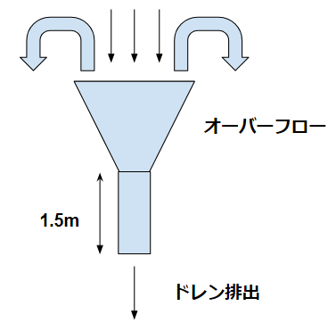
As a result, liquid can accumulate and overflow from the funnel.
This example illustrates an important point:
Batch discharge should be evaluated based on the transient discharge volume, not only the steady-state flow rate.
For batch plants, this distinction can be particularly important.
How to Prevent Drain Funnel Overflow
If a drain funnel is already installed and liquid is splashing or overflowing during operation, several countermeasures may be considered.
One option is to reduce the flow velocity from the pump.
Another is to install an orifice or similar restriction at the process-pipe outlet to reduce the discharge pressure and velocity.
However, both approaches can affect the operating conditions of the process or utility system, so they cannot necessarily be applied without further review.
Another practical approach is to install a cover above the reducer or funnel.
A cover can help contain splashing and prevent liquid from escaping into the surrounding area even when the discharge itself cannot easily be changed.
However, the cover should not be regarded as a substitute for proper hydraulic design. The design should first consider whether the funnel and drain system can safely accommodate the expected discharge.
Conclusion
A drain funnel may look like a simple piping component, but its design involves several factors that are easy to overlook.
The most important point is to consider the entire flow path:
Process piping → discharge/reducer → funnel → drain piping
For continuous discharge, the drain line must have sufficient capacity for the steady flow rate.
For batch discharge, the designer must also consider the short-term discharge volume and pressure release behavior.
In addition, the number of connected pipes, discharge pressure, velocity, temperature, and downstream drainage conditions can all affect the possibility of splashing or overflow.
In chemical plants, these seemingly minor details can eventually become operational or safety problems. Therefore, when designing a drain funnel, it is worth asking not only “Is the funnel physically large enough?” but also “Can the entire drainage system safely handle the actual discharge condition?”
About the Author – NEONEEET
A user‑side chemical plant engineer with 20+ years of end‑to‑end experience across design → production → maintenance → corporate planning. Sharing practical, experience‑based knowledge from real batch‑plant operations. → View full profile



Comments