In agitator vessel design, shaft strength calculation is essential.
If this step is neglected, the agitator shaft may fail or even break during operation.
This article explains agitator shaft strength calculation step by step, starting from basic concepts such as torsional moment and bending moment, and ending with how to determine shaft dimensions.
The goal is to help owner engineers and design beginners gain enough understanding to perform basic calculations on their own.
Agitator Design Basics: Understanding Power per Unit Volume (Pv) and Motor Power
What Is Critical Speed in Agitators? Resonance Principles and Practical Calculations
Mixing Power Calculation for Agitated Tanks: A Practical Guide for Plant Engineers
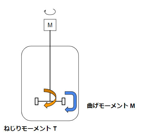
Moments Acting on an Agitator
The first step in agitator strength calculation is determining the moments acting on the shaft.
There are two main types:
- Torsional moment
- Bending moment
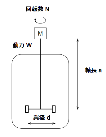
A typical agitator geometry is assumed for the following explanations.
Torsional Moment
The torsional moment T acting on the agitator shaft is generally calculated as:
T = 30W / (πN)
Where:
- W = agitator power
- N = rotational speed (rpm)
Relationship Between Power and Torque
This formula may feel confusing at first, so let’s review the dimensional relationship.
- Power unit: kg·m²/s³
- Torque unit: kg·m²/s²
This leads to the fundamental relationship:
Power = Torque × Frequency
Using the relationship between rotational speed and angular frequency:602πN=30πN
We obtain:
W = T × (πN / 30)
Rearranging gives the torsional moment formula shown above.
Bending Moment
Next, we calculate the bending moment M.
In practical agitator design, the bending moment is often assumed to be approximately one-third of the torsional moment, adjusted by geometry:
M = (1/3) × T × (d / 2a)
Where:
- d = impeller diameter
- a = shaft length
For shaft length a, a simple and conservative definition is the distance from the bearing to the bottom of the impeller.
If detailed drawings are unavailable, using the full shaft length (including motor side) is acceptable and safer.
The coefficient 1/3 may vary depending on agitator type, but it is commonly used as a practical assumption.
Important point:
Do not interpret this as torsional moment being converted into bending moment.
Instead, the bending moment is treated as an additional load acting simultaneously with torsion.
Equivalent Torsional Moment
Once torsional and bending moments are known, the equivalent torsional moment can be calculated as:Te=T2+M2
This is a standard textbook formula.
Equivalent Bending Moment
Similarly, the equivalent bending moment is calculated as:Me=21(M+T2+M2)
Again, this follows classical strength-of-materials theory.
Determining Shaft Dimensions
Using the equivalent moments, shaft dimensions can be determined based on:
- Maximum normal stress
- Maximum shear stress
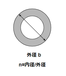
For a hollow circular shaft, the following formulas apply:σmax=πb3(1−n4)32Me τmax=πb3(1−n4)16Te
Where:
- b = shaft outer diameter
- n = inner-to-outer diameter ratio
Practical Shaft Sizing
In practice, it is recommended to include a 10–20% safety margin when selecting shaft dimensions.
Agitator shafts are usually fabricated from standard pipe sizes, so only a limited number of outer diameters and thicknesses are available.
An important practical point:
- Shaft strength depends only on power and geometry
- Fluid properties affect the required agitator power
- Once power is determined, shaft size follows
Rough Calculations Are Acceptable
Agitator shaft strength calculations rely on several assumptions:
- Bending moment coefficient (e.g., 1/3)
- Shaft length definition
- Safety margin
Although the formulas come from strength-of-materials theory, engineering judgment plays a major role.
Some engineers may feel uncomfortable with these approximations, while others find them practical and efficient.
With experience, many engineers come to appreciate that rough but conservative calculations are often sufficient in real projects.
Summary
- Agitator shaft strength calculation starts with understanding torsional and bending moments
- Equivalent moments allow safe determination of shaft dimensions
- In practical design, simple calculations with safety margins are sufficient
- Owner engineers and design beginners should be able to perform these calculations independently
Understanding the meaning behind the equations—not just applying them—leads to safer and more reliable agitator design.
About the Author – NEONEEET
A user‑side chemical plant engineer with 20+ years of end‑to‑end experience across design → production → maintenance → corporate planning. Sharing practical, experience‑based knowledge from real batch‑plant operations. → View full profile
Comments