Agitators used in chemical plants can reach critical speed if operating conditions are poorly selected.
At or near critical speed, vibration and resonance may occur, significantly increasing the risk of shaft failure.
Critical speed analysis is often left entirely to equipment manufacturers. However, if users do not understand the basic concept, it becomes difficult to ensure safe operation or prevent trouble in the field.
This article explains:
- The basic principle of critical speed and resonance
- Simple calculation methods suitable for practical use
- Important precautions during partial liquid (run-down) operation
Critical speed evaluation should always be considered together with agitator shaft strength calculations.
Agitator Design Basics: Understanding Power per Unit Volume (Pv) and Motor Power
Beginner’s Guide to Agitator Shaft Strength Calculation
Mixing Power Calculation for Agitated Tanks: A Practical Guide for Plant Engineers
Agitator Structure Assumed for Analysis
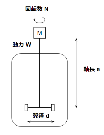
To explain critical speed, we assume a typical vertical agitator used in stirred tanks.
The agitator is modeled as:
- A vertical shaft
- An impeller mounted near the bottom
- Supported at the top by bearings
This simplified model is sufficient for practical evaluation.
Why Critical Speed Must Be Evaluated
Critical speed is commonly associated with resonance.
Even if the applied force itself is small, periodic excitation can cause vibration to grow over time.
By the time the vibration is noticed, the shaft may already be damaged or broken.
Vibration problems are critical in machinery and structures—and agitators are no exception.
During operation, fluid forces continuously excite the agitator shaft.
To ensure that the agitator operates safely without failure:
- Shaft strength must be evaluated
- Critical speed must be confirmed to be safely separated from operating speed
Critical Speed Calculation
The critical speed of an agitator shaft can be estimated using shaft deflection.
A commonly used practical formula is:Nc=2π60δg
Where:
- Nc = critical speed (rpm)
- g = gravitational acceleration
- δ = shaft deflection
Shaft Deflection
Shaft deflection is calculated using a modified cantilever beam model:δ=3EI(W1+0.236W2)a3
This equation is based on the classic cantilever beam deflection formula:δ=3EIWa3
Equivalent Weight
The difference lies in the numerator, which accounts for the actual agitator geometry.
- W₁ = impeller weight
- W₂ = shaft weight
Both are calculated simply as density × volume.
At the user level:
- Shaft weight can usually be estimated reasonably from drawings
- Impeller weight often requires assumptions
Because the impeller weight dominates the equivalent weight, some uncertainty is unavoidable.
Acceptance Criteria
Critical speed should always be evaluated with a safety margin.
A common and practical criterion is:N=0.8Nc
Operating speed should be below 80% of the first critical speed.
Estimating critical speed conservatively (lower) is safer.
Higher vibration modes exist at higher frequencies, so operating below the lowest mode avoids resonance during normal operation.
It is also good practice to check shaft deflection:δ≤100a
In most cases, the critical speed criterion is more restrictive than the deflection limit.
Partial Liquid (Run-Down) Operation
The formulas above rely on major simplifying assumptions, especially regarding operating conditions.
Dry Operation
If resonance occurs during dry operation, the agitator design is unacceptable.
In typical chemical plants:
- Operating speeds are on the order of 100 rpm
- Critical speeds are designed to be well above operating speed
For dry operation, mechanical seal wear is usually a greater concern than critical speed.
Liquid-Filled and Intermediate Conditions
The key parameter that changes with liquid level is the equivalent weight.
| Operating Condition | Equivalent Weight |
|---|---|
| Dry operation | W₁ + 0.236W₂ |
| Fully flooded | Approximately the same |
| Intermediate liquid level | W₁ increases effectively |
When fully flooded:
- Fluid resistance suppresses shaft deflection
- Smaller deflection → higher critical speed (safer)
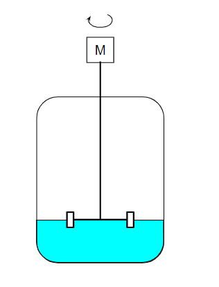
Why Partial Liquid Operation Is Dangerous
The most dangerous condition occurs when:
- The impeller is partially immersed
- The shaft is no longer stabilized by surrounding liquid
In this case:
- Effective impeller weight increases
- Shaft deflection increases
- Critical speed decreases
For example, consider draining liquid from the bottom of a tank while the agitator is running.
As the liquid level drops, the system will inevitably pass through this dangerous condition.
If the critical speed falls below the operating speed, resonance may occur.
This type of operation is known as run-down (partial liquid) operation.
Practical Countermeasures
Common countermeasures include:
- Installing an inverter (VFD) to reduce rotational speed
- Stopping the agitator during liquid discharge if speed control is unavailable
If speed cannot be adjusted, partial liquid operation should be avoided entirely.
Summary
Key points regarding agitator critical speed:
- Critical speed can be estimated using shaft deflection and equivalent weight
- Operating speed should be kept below 80% of critical speed
- Partial liquid (run-down) operation presents the highest risk
- Speed control or temporary shutdown is essential for safe operation
Always operate agitators with resonance avoidance in mind.
This awareness directly contributes to safer operation and longer equipment life.
About the Author – NEONEEET
A user‑side chemical plant engineer with 20+ years of end‑to‑end experience across design → production → maintenance → corporate planning. Sharing practical, experience‑based knowledge from real batch‑plant operations. → View full profile
Comments