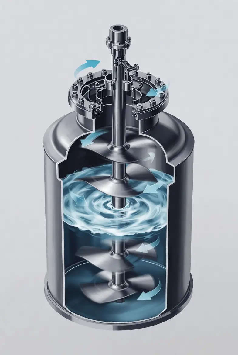
In chemical plants, agitators and mixing tanks are among the most common pieces of process equipment. Mechanical engineers frequently work with them, yet many have only a limited understanding of how liquid actually moves inside a stirred vessel.
Understanding flow patterns is far more important than memorizing impeller types. Once engineers can visualize how fluid circulates inside a tank, concepts such as scale-up, suspension, heat transfer, reaction efficiency, and mixing performance become much easier to understand.
This article introduces the fundamentals of agitator flow patterns from a practical engineering perspective, including discharge flow, circulation flow, radial and axial flow, vortex regions, baffles, and particle suspension.
- Why Mixing Performance Matters
- Discharge Flow and Circulation Flow
- Shear Rate
- Radial Flow vs. Axial Flow
- Impeller Position Matters
- Solid Body Rotation and Free Vortex Regions
- Why Baffles Are Essential
- Particle Suspension
- Just-Suspended Speed
- Typical Mixing Applications in Batch Chemical Plants
- Practical Engineering Perspective
- Conclusion
- About the Author – NEONEEET
Why Mixing Performance Matters
When engineers discuss agitator performance, they often ask a simple question:
“How do we measure a good mixer?”
Several performance indicators exist, but for most batch chemical processes, the most practical one is agitator power.
Mixing power is closely related to process scale-up. A laboratory flask can produce excellent reaction results, but reproducing those results in a reactor thousands of times larger is never straightforward.
The reason is simple.
Different physical phenomena scale differently.
- Production capacity depends on volume
- Heat transfer depends on surface area
- Reaction rates often depend on interfacial area
- Gas-liquid reactions depend on contact area
Because surface area increases with the square of length while volume increases with the cube, no scale-up method can preserve every physical relationship simultaneously.
For this reason, chemical engineers commonly maintain constant power input per unit volume as a practical compromise during scale-up.
Although not mathematically perfect, this approach usually produces similar overall mixing behavior.
Discharge Flow and Circulation Flow
Every impeller creates two major types of flow.
Discharge Flow
Discharge flow is the high-velocity liquid leaving the impeller blades directly.
It represents the primary driving force generated by the impeller.
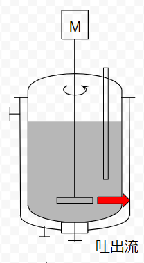
Circulation Flow
Circulation flow is the larger flow loop produced as the discharge jet entrains surrounding liquid.
The basic sequence is intuitive:
Impeller rotation → discharge jet → tank-wide circulation
If you’ve ever stirred water in a bathtub or mixed coffee with a spoon, you’ve already observed this principle.
Generally,
- Impeller geometry determines discharge flow.
- Stronger discharge flow produces stronger circulation.
- Better circulation creates more uniform mixing.
However, faster flow is not always better.
Some processes require gentle circulation, while others require intense turbulence.
Shear Rate
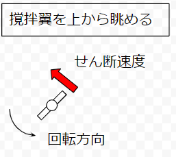
Another important mixing parameter is shear rate.
In practical terms, shear rate is closely related to the impeller tip speed.
Higher tip speed generally means:
- Faster discharge flow
- Stronger circulation
- Greater local turbulence
Large impellers naturally generate higher tip speeds.
Therefore, during scale-up, engineers often reduce rotational speed while increasing impeller diameter to maintain appropriate mixing conditions.
Radial Flow vs. Axial Flow
Impeller design strongly influences the direction of discharge flow.
Two basic flow patterns dominate industrial mixing.
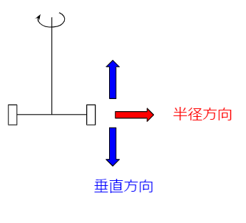
Radial Flow
Radial-flow impellers push liquid outward from the shaft toward the vessel wall.
Typical examples include:
- Paddle impellers
- Rushton turbines
- Flat-blade disk turbines
The mechanism is easy to visualize.
As the impeller rotates, centrifugal force drives the liquid outward.
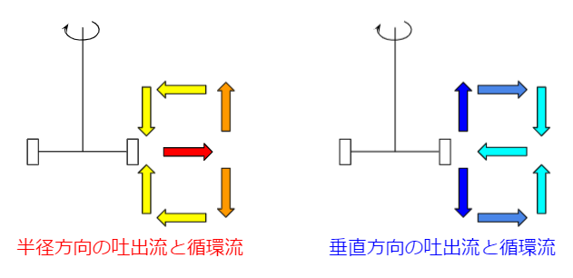
Axial Flow
Axial-flow impellers move liquid parallel to the shaft.
Propeller-type impellers are the most common example.
Instead of throwing liquid sideways, they pump it upward or downward through the vessel.
Axial flow often provides excellent bulk circulation.
However, in many batch chemical plants handling slurries, excessive downward flow may encourage particle accumulation near the vessel bottom if the system is not properly designed.
Impeller Position Matters
Flow patterns depend not only on impeller geometry but also on impeller location.
When an impeller is positioned close to the vessel bottom, downward circulation quickly encounters the tank floor.
This changes both discharge flow and circulation flow.
Large industrial reactors sometimes install multiple impellers along a single shaft to produce more uniform mixing throughout tall vessels.
Solid Body Rotation and Free Vortex Regions
Looking at the vessel from above reveals another useful concept.
The rotating liquid can be divided into two regions.
Solid Body Rotation
Near the impeller, the liquid rotates almost together with the blades.
The liquid behaves similarly to a rotating solid body.
Its velocity is largely determined by impeller diameter and rotational speed.
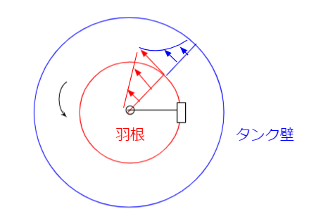
Free Vortex Region
Outside this region, liquid motion becomes more complicated.
Flow is influenced not only by impeller motion but also by:
- Fluid viscosity
- Density
- Tank geometry
- Turbulence
Higher viscosity weakens discharge flow, causing circulation to decay more rapidly.
Why Baffles Are Essential
Most industrial mixing tanks include vertical baffles.
Without them, the liquid tends to rotate together with the impeller, producing a large vortex while reducing effective mixing.
Baffles intentionally disturb this rotational motion.
As a result:
- Solid-body rotation decreases.
- Circulation patterns become more complex.
- Mixing becomes more uniform.
- Power consumption increases.
A simple analogy is stirring coffee.
Without any obstruction, the entire cup spins together.
If a spoon remains inside the cup while stirring, it acts like a baffle and immediately changes the flow pattern.
Particle Suspension
Many batch chemical processes handle slurries.
For these systems, particle suspension becomes a key design objective.
Two different situations should be distinguished.
One is when particles simply remain off the bottom.
The other is when particles are uniformly distributed throughout the vessel.
Uniform suspension requires considerably better mixing.
The primary factors affecting suspension include:
- Impeller diameter
- Impeller geometry
- Rotational speed
- Particle size
- Particle density
- Liquid viscosity
Among these, discharge velocity is often the most direct operational parameter.
Just-Suspended Speed
As impeller speed increases, progressively more particles become suspended.
Eventually, a speed is reached where every particle is lifted from the vessel bottom.
This operating point is known as the just-suspended speed.
It is an important design concept in slurry processing and crystallization systems.
Typical Mixing Applications in Batch Chemical Plants
Most batch reactors fall into one of four categories:
- Liquid-liquid mixing
- Gas-liquid mixing
- Solid-liquid mixing
- Homogeneous liquid storage
Among these, liquid-liquid and solid-liquid mixing are the most common.
Reaction, extraction, washing, crystallization, and slurry processing all rely heavily on effective agitation.
Fortunately, these operations are usually performed with well-established impeller designs rather than highly specialized equipment.
Practical Engineering Perspective
Although mixing theory can become mathematically complex, practical engineering often starts with visualization rather than equations.
If engineers can picture:
- where liquid leaves the impeller,
- how circulation develops,
- how baffles redirect flow,
- and how particles move inside the vessel,
they can make much better decisions about equipment selection, troubleshooting, and process optimization.
Understanding flow patterns is therefore one of the most valuable foundations for anyone working with batch chemical reactors.
Conclusion
Agitator flow patterns are the foundation of mixing performance in chemical plants. Rather than focusing only on impeller types or empirical correlations, engineers benefit most from understanding how liquid actually moves inside the vessel. Concepts such as discharge flow, circulation, radial and axial flow, baffle effects, and particle suspension explain why certain mixer designs work better for specific processes. Once these flow mechanisms become intuitive, troubleshooting, equipment selection, and process scale-up become significantly easier.
About the Author – NEONEEET
A user‑side chemical plant engineer with 20+ years of end‑to‑end experience across design → production → maintenance → corporate planning. Sharing practical, experience‑based knowledge from real batch‑plant operations. → View full profile



Comments