“How much flow rate can we expect when draining liquid from a tank?”
This question comes up from time to time, especially when operators want to confirm safety before performing a draining operation in the field.
At first glance, the calculation may seem simple, but in reality it requires more than mental arithmetic.
In this article, I introduce a hand-calculation-level method that can be used for quick checks on site.
When you face this situation, the key is to slow down and think calmly.
This article is part of a piping flow rate calculation series and a fluid mechanics series for chemical plant engineers.
How to Use Pipe Headers in Batch Chemical Plants: A Beginner’s Guide
Upward vs. Downward Pipe Branches: Which One Is Better for Your Plant?
What Is Average Flow Velocity in Pipes? A Simple Guide for Beginners
Pipe Tracing vs. Jacketed Piping: What’s the Difference? (Beginner’s Guide)
Why Pipe Supports in Chemical Plants Are Not So “Simple”
How Pipe Diameter Affects Flow Rate: A Simple Guide for Beginners
Target Model
We consider a system where a hose is attached to the bottom of a tank and liquid is discharged to the outside.
Using a hose is often necessary to:
- Concentrate discharged liquid at a specific location
- Avoid releasing liquid onto walkways or work areas
Note that this system behaves slightly differently from direct discharge without a hose.
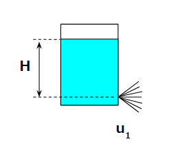
Case 1: Discharge Without a Hose
Our objective is to calculate the flow rate.
To do this, we must first determine the flow velocity.
The velocity can be obtained using energy conservation.
Assuming no losses, the potential energy at the liquid surface equals the kinetic energy at the discharge point:
$$ ρgH = \frac{1}{2}ρ{u_1}^2 $$
$$ u_1=\sqrt{2gH} $$
$$ Q_1 = \frac{π}{4}D^2u_1 $$
Here, D is the diameter of the discharge nozzle.
This completes the calculation for the hose-free case.
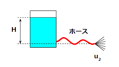
Case 2: Discharge with a Hose
When a hose is attached, the calculation changes.
Although the liquid level in the tank remains the same, pressure loss in the hose must be considered.
$$ ρgH = \frac{1}{2}ρ{u_2}^2 + 4f\frac{1}{2}ρ{u_2}^2\frac{L}{D} $$
$$ u_2=\frac{\sqrt{2gH}}{\sqrt{1+4f\frac{L}{D}}} $$
Only one additional term is added, but this significantly complicates the calculation.
As a result, people are often tempted to ignore the hose and use the hose-free result instead.
Whether that shortcut is acceptable depends on the situation.
Numerical Example
Let’s calculate with actual numbers.
Assumptions:
- Liquid head: H = 1 m
- Diameter: D = 0.05 m
Without a Hose
$$ u_1=\sqrt{2*9.8*1}=4.5 m/s$$
$$ Q_1 = \frac{π}{4}*0.05^2*4.5*1000*60=521L/min $$
This roughly matches the rule of thumb that a 50A pipe at 1 m/s gives about 100 L/min.
With a Hose
Assume:
- 4f = 0.04
- Hose length L = 10 m
$$ 4f\frac{L}{D}=0.04*\frac{10}{0.05}=8 $$
$$ u_2=\frac{4.5}{\sqrt{1+8}} =1.5m/s$$
$$ Q_2 = \frac{π}{4}*0.05^2*1.5*1000*60=174L/min $$
Simply adding a hose dramatically reduces flow rate.
Even if the hose is smoother (e.g., 4f = 0.01), the velocity only increases to about 2.6 m/s.
This shows how strongly hose resistance affects the result.
How to Think About Losses
In this example, properly estimating pressure loss is essential.
While hose friction is an obvious loss, it is surprisingly easy to forget even this term when calculations are rushed.
Other factors to consider are summarized below.
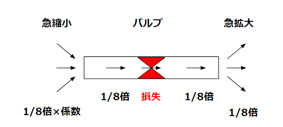
Sudden Contraction at the Nozzle
In the hose-free case, contraction losses at the nozzle are ignored.
Simple calculations assume:
- Velocity remains constant
- Flow rate changes only with diameter
In reality, smaller nozzles introduce additional losses due to sudden contraction.
These losses include coefficients and are rarely calculated in field-level hand calculations.
Sudden Expansion Loss
At the outlet, sudden expansion causes pressure loss.
$$ \frac{1}{2}ρu^2 $$
Including this term results in:
- Without hose: 3.2 m/s, 370 L/min
- With hose: 1.4 m/s, 162 L/min
When major losses such as hose friction exist, expansion losses have a smaller impact.
Throttling with a Valve
If a valve is installed before or after the hose and is throttled, valve pressure loss must be considered.
$$ ρgH = \frac{1}{2}ρ{u}^2+\frac{1}{2}ρ{u}^2 $$
$$ u=\sqrt{gH} $$
This is equivalent to changing the nozzle diameter.
For example:
- 50A valve fully open → 370 L/min
- Throttled to 25A equivalent → about 93 L/min
In such cases, valve loss dominates hose and expansion losses.
Conclusion
This article introduced a practical method for estimating flow rate when draining liquid from a tank using a hose.
Key points:
- Energy conservation is the starting point
- Hose friction significantly reduces flow rate
- Sudden expansion, contraction, and valves may or may not matter depending on the case
This approach is suitable for quick, on-site checks using hand calculations in chemical plant design, operation, and maintenance.
Questions and comments from the field are always welcome.
About the Author – NEONEEET
A user‑side chemical plant engineer with 20+ years of end‑to‑end experience across design → production → maintenance → corporate planning. Sharing practical, experience‑based knowledge from real batch‑plant operations. → View full profile
Comments