Pipe spacing is one of the most basic — yet most overlooked — aspects of piping design in chemical plants.
If you get it wrong, you’ll face interference, poor accessibility, and even costly rework during installation.
Many designers struggle with the same dilemma:
“I want to save space, but not so much that maintenance becomes impossible.”
This article explains the key design principles for determining minimum pipe spacing, with real examples and practical guidelines.
1. Parallel Piping
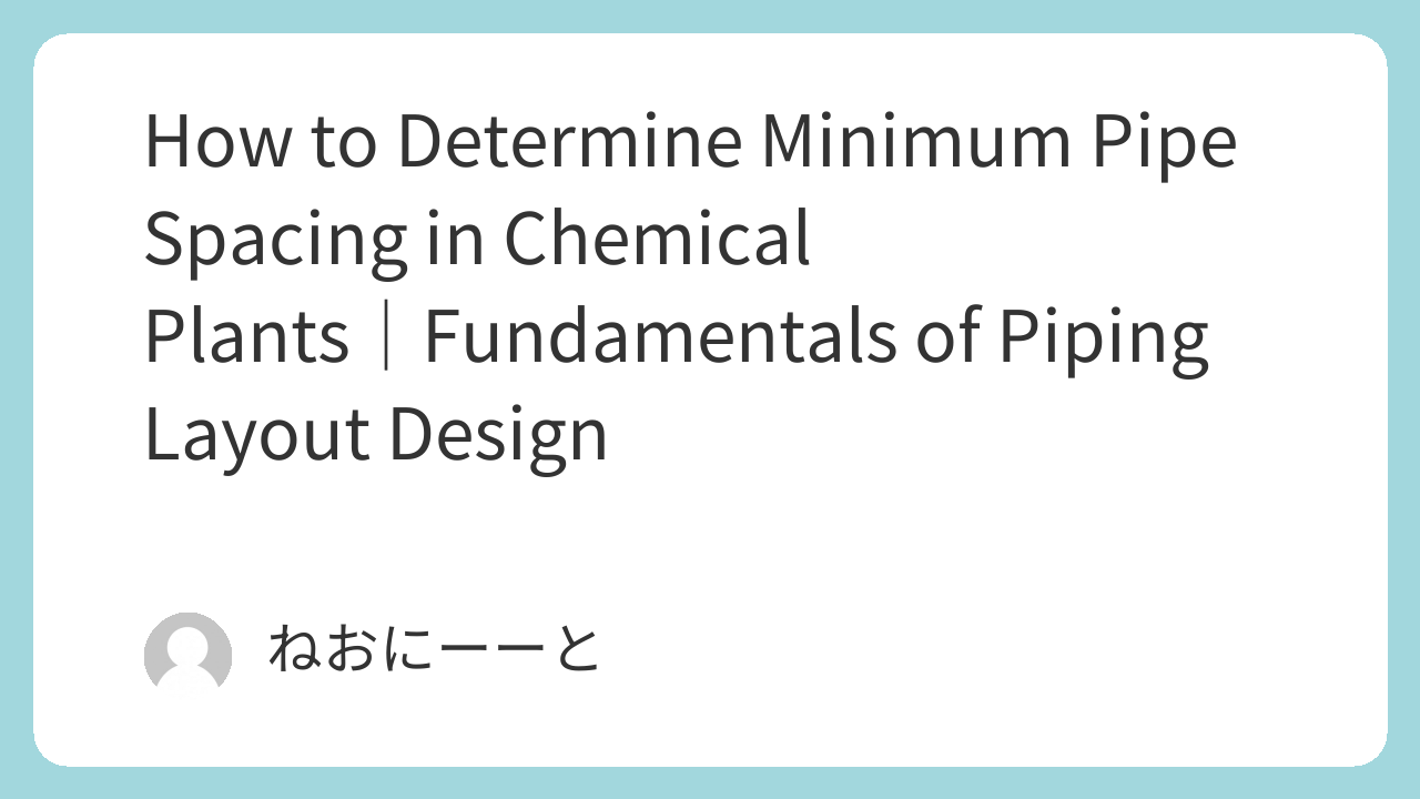
When multiple pipes run side by side — such as on a pipe rack or stand — always ensure there’s enough clearance for physical installation.
The basic rule is that flanges on adjacent pipes should not touch.
For example, with JIS 10K flanges:
Minimum distance = (Flange OD of Pipe A / 2) + (Flange OD of Pipe B / 2) + Work space allowance
Typical workspace: 25–30 mm for small-diameter piping.
2. Staggered Arrangement
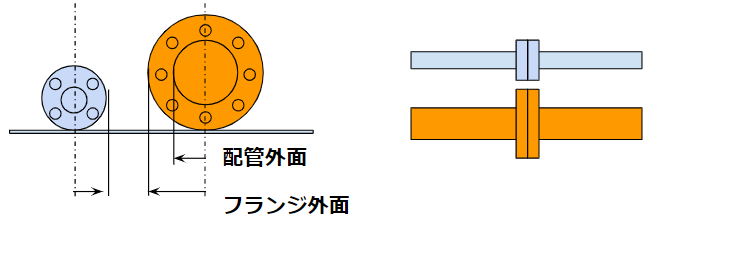
When space is tight, consider a staggered (chidorii) arrangement — offsetting the flanges so they don’t line up directly.
This allows closer spacing without interference.
In this case:
Distance = (Flange OD of larger pipe / 2) + (Outer diameter of smaller pipe / 2) + Work space
Be cautious with insulation and tracing, which can reduce available space.
3. Insulated Piping
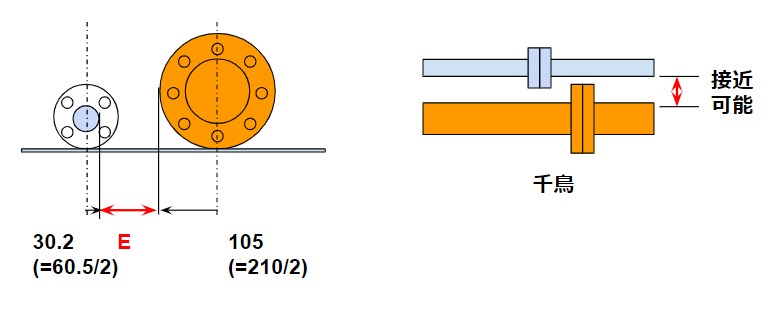
Once insulation is added, the required spacing increases.
Always include the insulation thickness and flange cover when calculating.
If both lines are insulated:
Distance = (Flange OD + Flange cover thickness) + (Pipe OD + Insulation thickness) + Work space
Adding steam tracing or jacket piping requires even more margin — don’t forget to check actual flange types to avoid misalignment.
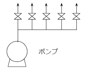
4. Headers and Valves
Headers, such as pump suction/discharge or tank lines, usually include valves.
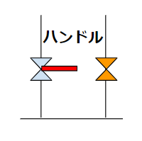
Here, clearance is not only for piping — you also need operation space for the valve handle.
A common mistake: handle interference between adjacent valves.
Always check handle dimensions for the exact manufacturer and valve type.
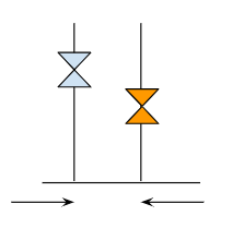
5. The “Stagger Trap” in Headers
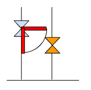
Trying to use staggered layouts for valve headers may seem efficient but can cause new problems.
When handles rotate, they might hit the neighboring valve — even if static spacing looks fine on CAD.
It’s often safer to use a simple inline arrangement with extra spacing for maintenance.
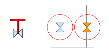
6. Gate and Globe Valves
Unlike ball or butterfly valves, these require less rotation clearance — but more working posture space.
Operators often need to shift position or use body weight, so consider ergonomics and safety when determining spacing.
Conclusion
Pipe spacing design might seem simple, but it’s deeply connected to constructability, operability, and safety.
Remember to:
- Avoid flange and valve interference
- Account for insulation and tracing
- Keep enough space for human operation
A few extra millimeters on paper can prevent huge problems during construction.
Design wisely — and always think about the people who will build and maintain your plant.
About the Author – NEONEEET
A user‑side chemical plant engineer with 20+ years of end‑to‑end experience across design → production → maintenance → corporate planning. Sharing practical, experience‑based knowledge from real batch‑plant operations. → View full profile
Comments