
Are you getting used to reading cross-section drawings?
In this article, we will look at the basic way to read a mechanical seal drawing.
If you can understand drawings at this level, you are already at a solid baseline for reading equipment drawings used in chemical plants. Some specialized equipment includes much more detailed cross-sections, but once you understand the fundamentals, you should eventually be able to interpret them—even if it takes some time.
How to Read Cross-Sectional Drawings: Understanding Mechanical Structures Through Color
How to Read Cross-Sectional Drawings: A Simple Coloring Method to Understand Mechanical Structures
How to Read Section Drawings (Part 3): Understanding a Shell-and-Tube Heat Exchanger Through Color Coding
Mechanical Seal Drawings Can Be Surprisingly Hard to Read
Mechanical seals are commonly used in centrifugal pumps and many other rotating machines.
Mechanical engineers working in chemical plants often look at these drawings during design work, maintenance planning, or troubleshooting.
Once you get used to them, mechanical seal drawings are actually simple. However, at first glance, the structure can be surprisingly difficult to interpret.
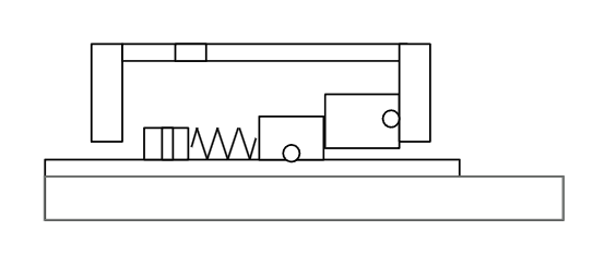
A typical cross-section drawing of a mechanical seal looks something like this.
If you can already visualize the parts and their functions from this diagram, you are already doing well.
Start Coloring the Obvious Parts
The easiest way to understand a drawing is to start with the most recognizable shapes.
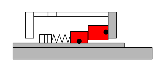
Mechanical seal drawings are usually composed of simple shapes such as circles and rectangles. Because of this, it helps to start by identifying and coloring the circular shapes first.

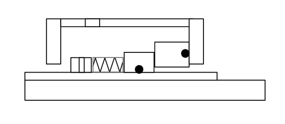
You may notice two circular elements in the drawing. These are most likely O-rings.
Since they are placed between two solid components and appear as circular shapes, it is reasonable to assume they function as sealing elements.
Although the sliding faces are the main sealing surfaces in a mechanical seal, secondary seals such as O-rings are just as important. Coloring these areas first helps you understand where leakage must be prevented.
For example:
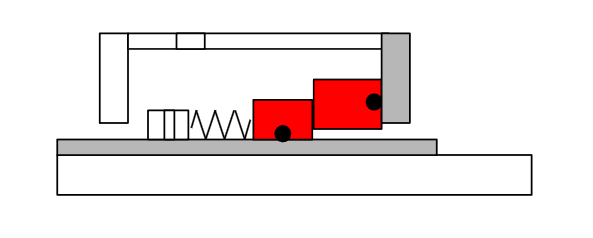
- The rotating ring can be colored red
- The sleeve can be colored gray
Even this simple step already makes the sliding interface easier to identify. Once you color the second set of components, the rotating ring and stationary ring become much clearer.
Extend the Coloring to Related Parts
After identifying the sliding faces, you can extend the coloring to nearby components.
Among the parts around the mechanical seal, the shaft is usually the largest component, so it is often easy to identify.
Once the shaft is colored, a new question naturally appears:
Which side is the pump side?
At first glance, the drawing may not make this obvious.
Understanding the Overall Structure
A mechanical seal sits at the boundary between the pump interior and the atmosphere.
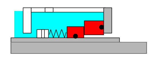
Because of this, one side of the drawing represents the pump side, while the other represents the atmospheric side.
In this example, the left side is the pump side.
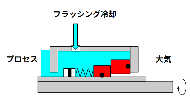
Since the pump contains liquid, it can help to color that area light blue to represent the process fluid. This makes it visually clear that the mechanical seal separates the liquid inside the pump from the outside environment.
This also makes it easier to imagine related elements such as:
- the metal components fixing the rotating ring
- the flushing fluid used to cool and lubricate the seal
Why Is the Left Side the Pump Side?
In this drawing, we can assume the left side is the pump side because the sleeve is not cut off in that direction.
The sleeve protects the shaft from wear and corrosion while it is exposed to the pump fluid.
If the pump side were on the right side of the drawing, the sleeve would appear partially missing, which would reduce its protective function. Because the sleeve is continuous toward the left side, that direction most likely faces the pump interior.
Pump Side vs Atmospheric Side Can Be Confusing
In some drawings, the sleeve discontinuity makes the orientation obvious.
However, many drawings do not show such clear hints.
In those cases, the drawing may explicitly label the sides as:
- Pump side
- Atmospheric side
Without these indicators, confusion can arise because different sealing arrangements are possible.
For example:
- Pump on the left side → inside flushing configuration
- Pump on the right side → outside quenching configuration
These conditions are usually described in the seal datasheet, but the datasheet and the drawing do not always perfectly match. Therefore, engineers should always double-check the consistency between documents.
For this reason, the coloring method is not just a learning trick—it is also a practical way to reduce mistakes when interpreting drawings.
Conclusion
Mechanical seal cross-section drawings can look complicated at first, making it difficult to understand which component performs which function.
However, by starting with recognizable parts such as O-rings and sealing faces, and gradually expanding your understanding to surrounding components like the shaft and sleeve, the overall structure becomes much easier to visualize.
In addition, thinking about the relationship between the pump side and the atmospheric side helps clarify how the mechanical seal isolates process fluid from the external environment.
Using colors to organize the drawing is therefore a simple but effective technique—not only for understanding the structure, but also for preventing mistakes when reading technical drawings.
About the Author – NEONEEET
A user‑side chemical plant engineer with 20+ years of end‑to‑end experience across design → production → maintenance → corporate planning. Sharing practical, experience‑based knowledge from real batch‑plant operations. → View full profile
Comments