One frequently overlooked point in chemical plant piping design is the distance between the flow meter and the control valve.
The positional relationship between a flow meter and a control valve directly affects the actual liquid charging volume and control accuracy. Keeping the distance between them as short as possible makes operational control easier. If they are not properly arranged, unexpected troubles and operational deviations may occur.
This article explains why minimizing this distance is important, along with practical design considerations.
In some cases, you may never encounter problems even without imagining these scenarios in advance. You might think it’s fine to deal with them after they occur. However, since these issues have happened many times in the past, having the foresight to anticipate them can help you apply accumulated experience effectively.
Why Vortex Flow Meters Are the Best Choice for Steam in Chemical Plants
Practical Methods to Estimate Utility Usage in Chemical Plants Without Flow Meters
Where Rotameters Work Best in Chemical Plants: Practical Use Cases for Engineers
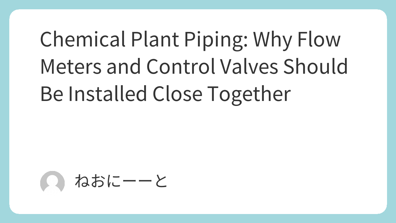
Distance Between Flow Meter and Control Valve
Let’s first confirm the basic arrangement. In principle, the flow meter is installed upstream, and the control valve is installed downstream.
This configuration ensures that the flow meter line remains completely filled with liquid. If the control valve is installed upstream, the flow meter will not provide accurate readings until the line becomes fully filled.
The focus here is that the distance between the flow meter and the control valve should be as short as possible. In practice, layouts often look like this:
Flow meters are frequently installed horizontally, while control valves are ideally installed as close as possible to the root (inlet) of the equipment. Following this concept often results in some separation between the two.
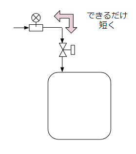
Difference Between Flow Meter Reading and Actual Charged Volume
Due to piping length, discrepancies arise between the flow meter reading and the actual volume delivered to the equipment. Let’s consider this from a time-trend perspective.
Even after the flow meter starts counting, there is a time delay before liquid actually reaches the equipment. This delay is determined by:
Piping length ÷ Flow velocity
Similarly, even when the flow meter reaches the target value and the valve closes, liquid does not instantly stop entering the equipment. The liquid remaining in the piping continues flowing into the equipment.
If a pump is used during transfer, flow velocity decreases when the control valve closes.
Now, what if we delay closing the control valve to compensate? Would “Flow meter indication = Actual charged volume”?
Not necessarily.
Liquid hold-up inside the piping must also be considered. The longer the piping, the larger the hold-up volume. The amount differs depending on:
- 1st batch (empty piping)
- 2nd and subsequent batches
- Final batch
To perfectly match readings across batches, all operations—including startup and cleaning—must be standardized. This is one of the complexities of batch operations.
If the flow meter is used for solvents where some error is acceptable, this may not be critical. However, for reactants requiring strict dosing accuracy, careful consideration is essential.
From this strict accuracy standpoint, vertically installed variable area flow meters (rotameters) can be disadvantageous.
Supplying Multiple Destinations
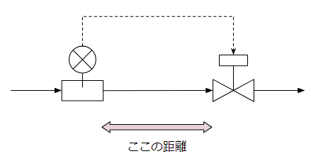
If one flow meter and one control valve are paired 1:1, minimizing the distance generally resolves most issues.
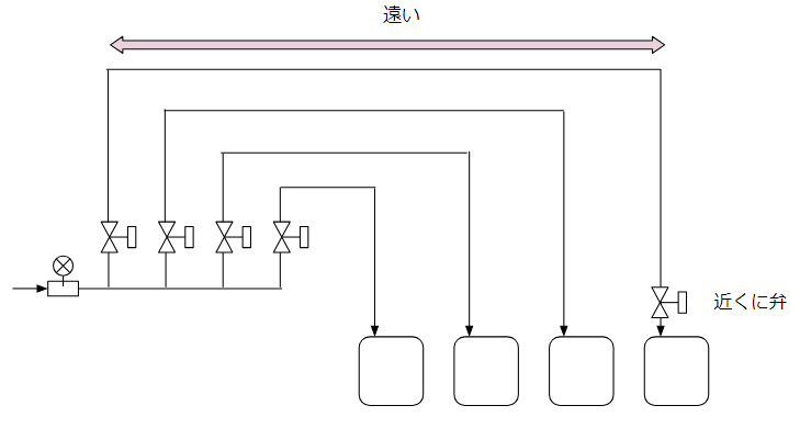
However, consider a batch operation where one flow meter supplies multiple pieces of equipment using a header system.
In such cases, the control valve should ideally be placed near the flow meter.
Possible issues include:
- Energy loss when the pump continues pushing liquid toward unused branches
- Air pockets forming in piping, causing discrepancies between flow meter readings and actual charged volume
- When supplying the lowest elevation line, opening the valve may cause liquid from other branches to flow in
These problems may not always occur—but if operational troubles arise, investigating piping and instrumentation issues can waste valuable time.
If the distance between the flow meter and control valve is long—even in header systems—consider installing a control valve near the equipment as well. Although adding automatic on-off valves increases cost, ensuring stable operation is more important.
Summary
The distance between a flow meter and a control valve is often underestimated in piping design.
By installing them close together, discrepancies between indicated and actual charged volume can be minimized, enabling stable operation.
Even in header piping systems supplying multiple units, careful positioning of control valves helps prevent operational problems.
When designing piping, prioritize operational stability—not just cost—when determining installation distances.
If you have questions or concerns about chemical plant design, maintenance, or operation, feel free to leave a comment.
All comments will be carefully reviewed and answered sincerely.
Comments