
When I was a junior engineer, I realized that the fastest way to truly understand a mechanical section drawing was simple: color it.
Surprisingly, very few engineers actually do this. It’s easy to feel like you understand a drawing—until you have to work independently or explain it to someone else. That’s when gaps in understanding become obvious.
In this article, we’ll use color coding to break down the outline drawing of a horizontal shell-and-tube heat exchanger and turn a complex drawing into a clear structural image.
How to Read Cross-Sectional Drawings: Understanding Mechanical Structures Through Color
How to Read Cross-Sectional Drawings: A Simple Coloring Method to Understand Mechanical Structures
How to Read a Mechanical Seal Cross-Section Drawing (Beginner Guide)
- Visualizing the Heat Exchanger
- The Actual Outline Drawing (Initial State)
- Step 1: Start With the Most Obvious Part — The Main Flanges
- Step 2: Expand From the Flanges — Channel Cover and Shell
- Step 3: The Final Step — Coloring the Tube Section
- Considering Drawing Detail and Scale
- Conclusion
- About the Author – NEONEEET
Visualizing the Heat Exchanger
Before looking at the actual drawing, it’s important to picture what a horizontal shell-and-tube heat exchanger looks like.

For beginners, the key is recognizing the tube bundle.
In a shell-and-tube exchanger, the tubes are the heart of heat transfer. Two separate fluids flow—one inside the tubes and one on the shell side—exchanging heat across the tube walls.
If you don’t have this image in mind, the drawing will look like nothing more than a collection of lines.
The Actual Outline Drawing (Initial State)
When you look at a typical outline drawing of a heat exchanger, it may resemble a dense technical sketch with many overlapping lines.
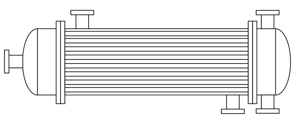
Even experienced engineers can feel uncertain when encountering a new type of equipment. That’s exactly when color coding becomes powerful.
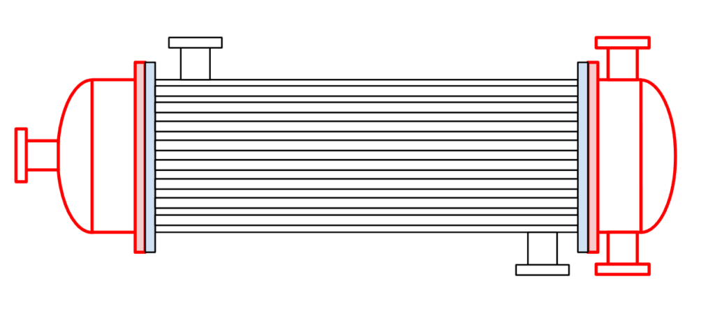
Step 1: Start With the Most Obvious Part — The Main Flanges
The basic rule of color coding is simple:
Start with the easiest part to identify.
In this case, that’s the main flanges.
A flange connects two components. It also represents a structural boundary. By coloring each flange—and using different colors for adjacent ones—you immediately clarify:
- Where components separate
- How assemblies are connected
- What belongs to which part
This creates the structural “skeleton” of the drawing.
Step 2: Expand From the Flanges — Channel Cover and Shell
After coloring the flanges, extend the color to the lines directly connected to them.
For example:
- The channel cover attached to the flange
- The shell connected on the opposite side
Because flanges mark boundaries, everything connected continuously to them typically belongs to the same component.
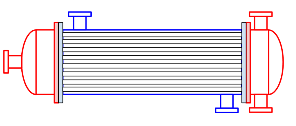
Once you do this, something important becomes visible:
- Tube-side nozzles
- Shell-side nozzles
At this point, you can clearly distinguish the two fluid paths—the fundamental principle of heat exchange.
If the tube side has one nozzle on the left and two on the right, for example, you might infer a phase-change process (such as condensation or evaporation). Even from an outline drawing, process insight becomes possible.
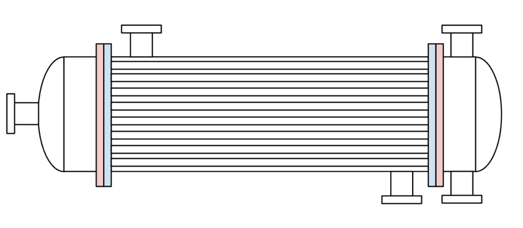
Step 3: The Final Step — Coloring the Tube Section
The most confusing area is usually the tube bundle.
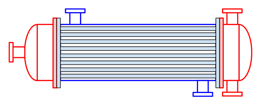
Without color, it looks like a cluster of parallel lines. But once you define boundaries, you can identify the repeating pattern:
- Void (fluid space)
- Solid (tube wall)
- Void (fluid space)
By following this pattern carefully, the tube bundle becomes clear.
When the coloring is done correctly:
- The tube-side flow path becomes visible
- The shell-side flow path becomes distinguishable
- The heat transfer interface is easy to imagine
The drawing transforms from “lines on paper” into a functioning piece of equipment.
Considering Drawing Detail and Scale
Some drawings show shell thickness or tube thickness clearly.
In more detailed, near-to-scale drawings, wall thickness can help confirm your interpretation.
If you get confused, return to three fundamentals:
- Identify boundaries
- Distinguish solid from void
- Visualize fluid flow
These principles rarely fail.
Conclusion
Coloring a drawing is not a childish exercise. It is a structured way to:
- Clarify component boundaries
- Separate solid material from flow space
- Visualize fluid paths
In equipment like a shell-and-tube heat exchanger, understanding the relationship between the tubes and the shell is foundational to design, construction, maintenance, and troubleshooting.
Don’t settle for “I think I understand it.”
Try physically coloring a drawing once. You may find your depth of understanding changes significantly.
About the Author – NEONEEET
A user‑side chemical plant engineer with 20+ years of end‑to‑end experience across design → production → maintenance → corporate planning. Sharing practical, experience‑based knowledge from real batch‑plant operations. → View full profile
Comments