A Distributed Control System (DCS) is a core element of plant automation.
Although it consists of many devices and can look complex at first glance, understanding its basic hardware architecture is essential for engineers working in industrial plants.
Mechanical engineers often have little direct involvement with DCS, but from a plant-wide perspective, it plays a critical role. Even a high-level understanding makes communication with instrumentation and control engineers much easier.
In this article, we explain the main hardware components of a DCS and their roles, using practical examples.
This guide is written for beginners who want to grasp the fundamentals of plant control systems without diving too deeply into control theory.
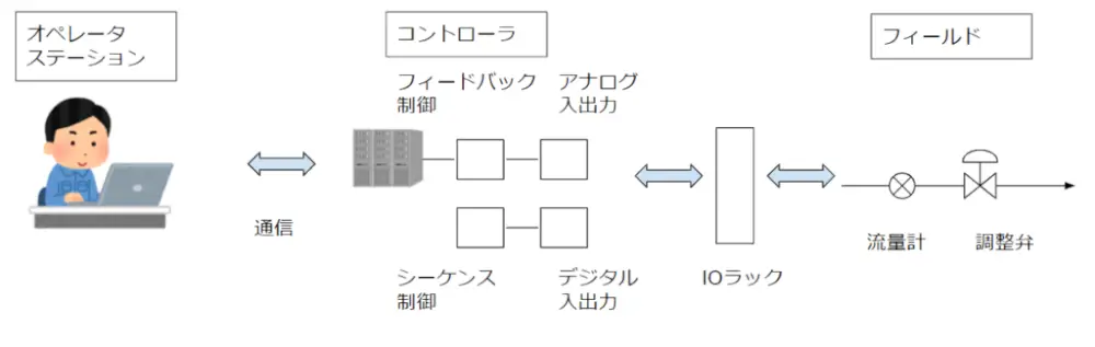
Overview of a DCS Hardware System
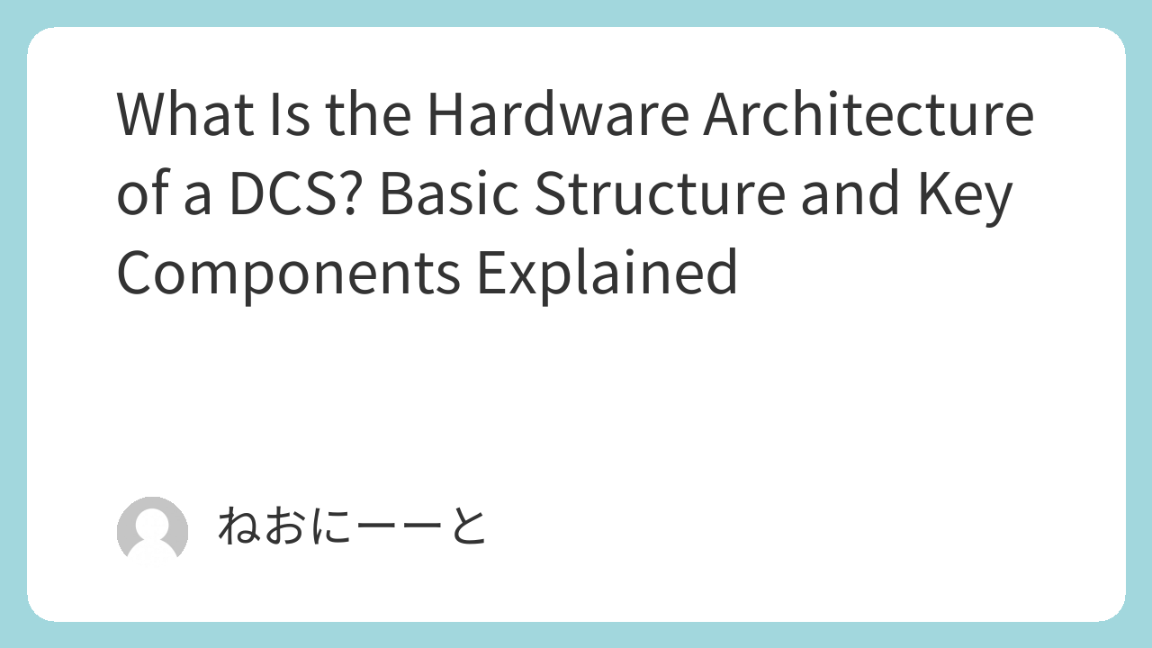
A DCS can be expressed with a simple system structure:
- Field (Plant Equipment)
Sensors, valves, and actuators installed in the plant - Control Stations
Collect field signals and execute control logic - Human Interface System (HIS)
Operator stations used for monitoring and control
Although the field level may appear small in diagrams, it is actually the largest and most important part of the system—both physically and operationally.
The control room, often shown in photos with many monitors and desks, is where the HIS and control stations are installed.
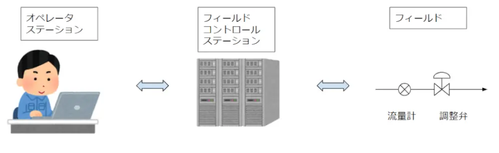
Control Section
The control section includes I/O racks and performs the following functions:
- Executes process calculations using CPUs
- Converts field signals into digital data
- Sends calculated control signals back to the field
In simple terms, feedback control (such as PID control) is completed within this section.
If a plant could operate without human intervention, this part alone would be sufficient.
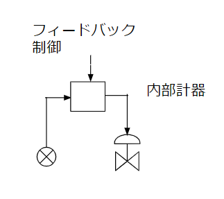
Operation and Monitoring Section (HIS)
Human operation and monitoring are still essential in real plants.
Typical HIS functions include:
- Graphics (process flow diagrams)
- Operator guidance messages
- Alarms
- Trends
- Tuning
- Group displays
Among these, graphics and trends are the most frequently used.
Trend displays are especially valuable for analyzing plant behavior over time and should also be used by mechanical engineers.
Alarm management is another critical topic. Too many alarms can overload operators, so alarm configuration has become an important engineering task.
Cabinets, Nests, and Cards
A “station” is a functional concept rather than a physical object.
Physically, DCS hardware is installed in cabinets (cubicles) located in an electrical or instrument room.
Each cabinet contains multiple nests, and each nest holds several cards (printed circuit boards).
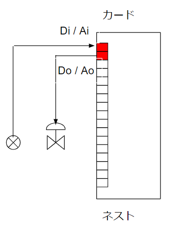
Types of Cards
Cards are the smallest functional units in a DCS and are typically classified into:
- Signal distribution cards
- Input/output (I/O) cards
- Control cards
For example, one card may be assigned to temperature measurement, while another handles control output for the same loop.
Functional Separation
DCS hardware is organized by function to improve efficiency and maintainability.
Typical classifications include:
- Analog / Digital
- Input / Output
- Process signals / Alarms / Interlocks
This functional separation is similar to how companies are organized into departments and teams.
Signal Input and Output
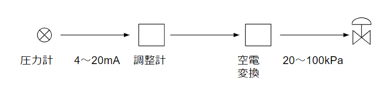
Analog Instruments
For analog control (e.g., temperature control):
- The sensor detects a process value
- The I/O card converts it into a control signal
- The controller calculates the control output
- The output signal is sent back to the field device
The commonly used signal standard is DC 4–20 mA.
Digital Instruments
Digital signals are mainly used for sequence control, such as:
- Tank level high → close feed valve
Unlike analog control, digital control does not use feedback loops.
Electrical and Pneumatic Signals
Modern plants rely almost entirely on electrical signals.
| Item | Electrical | Pneumatic |
|---|---|---|
| Transmission speed | Fast | Slow |
| Accuracy | High | Low |
| Data handling | Easy | Difficult |
Pneumatic signals are now rarely used except in specific cases.
Indication, Recording, and Alarms
Historically, indicators, recorders, and alarms were separate devices.
Today, most of these functions are handled by the DCS.
However, hard alarms are still used for certain equipment (e.g., refrigeration units) that operate independently from the DCS.
Power Supply
Instrumentation power is typically below 100 V, with DC 24 V being the most common.
- Analog signals: DC 4–20 mA
- Digital on/off signals: DI / DO
- Control valves: often powered by 100 V
Standardization is preferred to simplify maintenance and spare parts management.
Redundancy
Redundancy means having duplicate components to prevent total system failure.
In a DCS, redundancy is applied to:
- Control stations
- CPUs and memory
- Power supplies
- I/O cards
The system continuously performs self-diagnostics and automatically switches to backup components when faults occur.
DCS vs PLC (Sequencer)
- DCS
- Installed in the plant control room
- Controls overall plant operation
- Often programmed by plant engineers
- PLC (Sequencer)
- Used for specific machines (e.g., centrifuges, chillers)
- Control logic usually provided by the equipment manufacturer
Complex or specialized equipment is typically “handled outside” the DCS and connected via signal interfaces.
✅ Conclusion
A DCS hardware system consists of many components working together to achieve reliable plant control.
By understanding the basic hardware architecture, engineers can communicate more effectively, design systems more efficiently, and respond to troubleshooting situations with confidence.
This article provides a practical overview to help you grasp the overall picture of DCS hardware in real industrial plants.
About the Author – NEONEEET
A user‑side chemical plant engineer with 20+ years of end‑to‑end experience across design → production → maintenance → corporate planning. Sharing practical, experience‑based knowledge from real batch‑plant operations. → View full profile
Comments