When drawing or reviewing a mechanical cross-section, how do you use color?
Black-and-white drawings often make it difficult to distinguish component boundaries or material differences. As a result, explanations take longer, and understanding takes more effort.
You may have experienced this:
- “I can’t immediately visualize the structure.”
- “The geometry doesn’t stay in my head.”
- “My senior engineers understand it instantly, but it takes me time.”
In this article, I explain a simple yet practical technique: using color to clarify cross-sectional drawings and improve structural understanding.
This article is part of the Cross-Section Reading Series.
How to Read Cross-Sectional Drawings: A Simple Coloring Method to Understand Mechanical Structures
How to Read Section Drawings (Part 3): Understanding a Shell-and-Tube Heat Exchanger Through Color Coding
How to Read a Mechanical Seal Cross-Section Drawing (Beginner Guide)
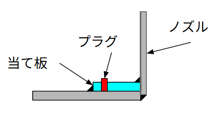
The Actual Nozzle and the Completed Drawing
Let us begin by looking at a real nozzle.
There are many reference images available online. Seeing the actual component first helps build a mental model before interpreting the drawing.
When the drawing is also divided by color, the relationship between the real object and the drawing becomes much clearer.
In the early stages of learning, many engineers feel uncertain:
“Does this drawing really represent the object correctly?”
I still remember the reassurance I felt when the drawing matched the actual equipment exactly as I had imagined. It was confirmation that my interpretation skills were improving.
Learning to read drawings properly gives you tangible growth as an engineer. Let’s build that skill step by step.
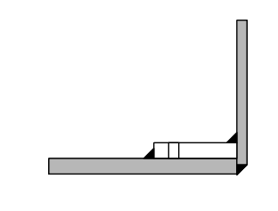
The Initial Drawing (Before Coloring)
On technical drawings, the nozzle may appear as a simplified enlarged view.
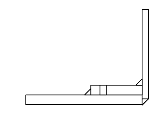
This type of enlarged detail is necessary to show how the nozzle is constructed, even though the overall assembly drawing may look simpler.
When you look at such a drawing, can you immediately visualize the real object?
Most people hesitate. That hesitation is precisely why coloring helps.
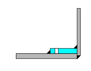
Start with the Most Understandable Area
The foundation of reading cross-sections is identifying boundaries and applying color.
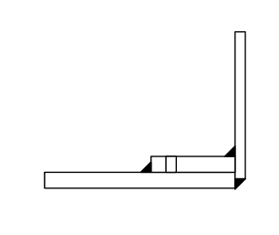
Begin with the most obvious element.
In this example, the weld area is the clearest starting point.
Even if the rectangular shapes are ambiguous at first glance, the triangular weld symbol provides a strong hint. Once you recognize the weld symbol, you can color the connected plates accordingly.
After coloring, it becomes much easier to see that three plates are joined by welding.
Understanding Boundaries
Coloring is essentially about identifying physical boundaries.
In this enlarged view, the rectangles represent:
- Tank shell
- Nozzle
- Reinforcement pad
Because it is an enlarged detail, the larger shapes typically correspond to larger structural members. Once you confirm where the weld connects them, the overall geometry becomes easier to imagine.
You may choose to color the reinforcement pad first instead, since it is smaller and distinct. Either approach works as long as you are consciously identifying boundaries.
For example, when coloring the reinforcement pad (excluding the plug area), the structural role of the part becomes clearer.
Once the weld location and boundary are understood, the function of the plug also becomes easier to interpret.
Color does not merely decorate a drawing—it reveals structure.
■ Summary
Reading cross-sectional drawings is not only about experience; it is about method.
By using color to clarify boundaries:
- Weld connections become clearer
- Structural members separate visually
- The overall geometry becomes easier to grasp
When the drawing and the actual object align in your mind, confidence grows.
Start with the most understandable part.
Identify boundaries.
Apply color deliberately.
With repetition, cross-sections become far less intimidating—and much more intuitive.
About the Author – NEONEEET
A user‑side chemical plant engineer with 20+ years of end‑to‑end experience across design → production → maintenance → corporate planning. Sharing practical, experience‑based knowledge from real batch‑plant operations. → View full profile
Comments