
When you look at a mechanical cross-sectional drawing, how do you actually read it?
In black and white, components blend together. Material boundaries are unclear. Moving parts and fixed parts are difficult to distinguish. And many engineers have experienced this:
- “I’m looking at the section view, but I can’t visualize it.”
- “The structure doesn’t stick in my head.”
- “Senior engineers grasp it instantly—why does it take me so long?”
One simple but highly effective solution is surprisingly low-tech: add color.
Coloring a cross-sectional drawing is not about aesthetics. It is a structured way to break down and interpret mechanical relationships. Let’s walk through the concept using a simplified cylinder example.
How to Read Cross-Sectional Drawings: Understanding Mechanical Structures Through Color
How to Read Section Drawings (Part 3): Understanding a Shell-and-Tube Heat Exchanger Through Color Coding
How to Read a Mechanical Seal Cross-Section Drawing (Beginner Guide)
Step 1: Start with the Most Obvious Component
Begin with the part you are absolutely certain about—typically the outer casing.
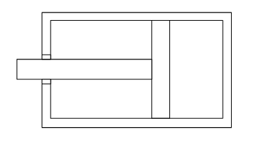
In section drawings, the outermost boundary represents the interface between solid material and atmosphere. The space between the two boundary lines indicates material thickness. By coloring this region first, you immediately define a structural reference frame.
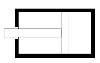
Starting with the clearest component reduces errors and builds confidence before tackling more ambiguous regions.
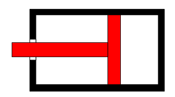
Step 2: Identify Adjacent Major Components
Next, examine the components connected to the casing. In a cylinder example, this would typically include the piston and rod.
Ask yourself:
- Is the rod exposed externally?
- Does the piston logically connect to it?
- Would this be welded, bolted, or integral?
Engineering judgment comes into play here. Instead of passively reading lines, you actively question the function and mechanical logic behind the geometry.
By assigning a different color (or shade), boundaries between moving and fixed components become clear.
Step 3: Resolve the Remaining Areas (Seals and Interfaces)
Once major components are defined, the remaining regions often represent seals or functional gaps.
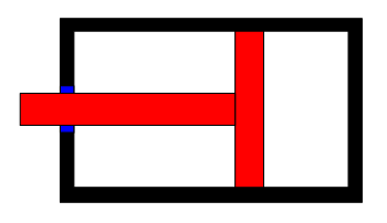
If a piston moves inside a casing, there must be sealing elements. Coloring these areas highlights the boundary between fixed and moving parts and helps you infer system behavior:
- Internal volume changes
- Pressure balance
- Flow paths
- Potential control mechanisms (pneumatic or hydraulic)
At this stage, the 2D drawing transforms into a mental 3D mechanism with dynamic behavior.
Why This Method Works
Coloring forces you to:
- Identify structural boundaries
- Distinguish solid from void
- Separate fixed and moving components
- Infer function from geometry
It turns passive viewing into active analysis.
In practice, you may only need to color a new type of equipment once or twice. After that, your brain builds the internal model automatically.
Conclusion
Adding color to a cross-sectional drawing dramatically improves structural comprehension and communication—without expensive software or complex standards.
If you struggle to visualize mechanical drawings, start simple:
- Color the most obvious part.
- Expand to connected components.
- Resolve the remaining functional regions.
This approach not only clarifies structure but also sharpens your engineering intuition.
About the Author – NEONEEET
A user‑side chemical plant engineer with 20+ years of end‑to‑end experience across design → production → maintenance → corporate planning. Sharing practical, experience‑based knowledge from real batch‑plant operations. → View full profile
Comments