
This article explains line specifications shown on P&IDs (Piping and Instrumentation Diagrams).
Line specifications are sets of information written directly on piping lines in a P&ID.
Although there is no strict universal standard, the items that should be included are mostly consistent across companies.
Line specifications contain a surprisingly large amount of information about piping.
In many cases, they even provide clues about how the plant is manufactured.
For complex systems such as batch plants, it is often impossible to determine the entire process based on line specifications alone.
However, in continuous plants, they are relatively easy to interpret.
Line specifications are created based on simplified flow diagrams, so they are often thought of as the responsibility of process engineers.
That said, mechanical and electrical engineers should also understand them, as they are essential for design, construction, and maintenance.
This article is part of the P&ID series.
How to Read P&ID Diagrams in Batch Chemical Plants – A Beginner’s Guide
Beginner’s Guide to P&ID Instrument Symbols – What Do Those Letters and Circles Mean?
P&ID Symbols 101 — How to Read Equipment, Piping and Valve Symbols (Practical Guide for Plant Engineers)
What Should Be Written in Line Specifications
Let’s organize the typical items included in line specifications.
In most cases, they are written in the following order:
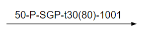
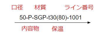
Pipe size – Fluid – Material – Insulation – Line number
(Some companies place the line number first, but this is less common.)
Pipe Size
In batch chemical plants, pipe size is often written using the A-size system, which is intuitive and close to millimeters.
Examples:
- 25A → approx. 25 mm
- 40A → approx. 40 mm
- 50A → approx. 50 mm
The actual outer diameter is slightly larger than the A-size value, but the difference is usually negligible.
In continuous plants, B-size (inch-based) notation is more common because pipe diameters are larger.
Examples:
- 100A → 4B
- 200A → 8B
- 400A → 16B
This approach avoids large numbers, similar to choosing MPa instead of kPa for pressure units.
For traced pipes or double pipes, additional information is often included.
For example, if a Φ12 copper trace pipe is attached to a 50A pipe, it may be written as:
50A / Φ12
Fluid
Fluid notation varies significantly by company because it may contain confidential information.
If the fluid is clearly identified, it may be possible to infer the manufacturing process from the P&ID alone.
To prevent information leakage, abbreviations are commonly used.
Typical examples include:
- P : Process fluid
- W : Water
- CW : Cooling water
- BW : Brine
- HW : Hot water
- FW : Fire water
- N : Nitrogen
- A : Air
- G : Gas
“P” (process fluid) may be subdivided further depending on company rules.
However, excessive detail can reveal the process itself, so caution is required.
Material
Material notation also varies by company.
For common piping materials, the material name is written directly.
Typical examples include:
- SGP
- STPG
- SUS304
- SUS316L
When multiple specifications exist for the same material, custom material codes are often used, such as SGP1, SGP2, etc.
Why distinguish them if the material is the same?
A common reason is different gasket specifications.
Even with identical pipe materials, using different gaskets requires clear differentiation in line specifications to avoid mistakes.
As the number of variations increases, management becomes more complex, so minimizing material codes is generally preferred.
Insulation / Heat Tracing
This section describes rules for insulation or cooling insulation.
Thickness
Thickness is the most important parameter.
If thickness alone is insufficient, temperature is also specified.
Example:
t30 (80)
→ 30 mm insulation thickness, fluid temperature 80°C
Personally, thickness alone is often sufficient, but practices vary.
Type
Insulation types must also be specified.
Thickness alone cannot distinguish between heat insulation and cold insulation.
Typical notation:
- H : Heat insulation
- C : Cold insulation
Examples:
- H30 → 30 mm heat insulation
- C30 → 30 mm cold insulation
Line Number
Line numbers are primarily used for managing piping drawings, rather than for P&IDs themselves.
In batch chemical plants, including line numbers on P&IDs often has little value because:
- Piping modifications are frequent
- Lines are constantly added and removed
- Number management becomes confusing over time
Line numbers on P&IDs are only meaningful when all of the following conditions are met:
- Piping drawings are well maintained and cross-checked with P&IDs
- Modifications and expansions are properly updated
- Line numbers are consistently managed after every P&ID change
For this reason, line numbers are often written on P&IDs during initial plant construction, but are poorly suited for long-term operation.
In continuous plants, where switching lines are rare, line numbers may still be practical.
However, including too much information in line specifications can reduce readability.
Conclusion
This article summarized what is typically written in P&ID line specifications.
Line specifications contain a significant portion of piping-related information.
If leaked externally, they can reveal manufacturing methods—making them extremely valuable technical data.
Understanding how to read and write line specifications correctly is essential for drawing creation, review, and long-term plant management.
If you have questions or concerns related to chemical plant design, maintenance, or operation, feel free to leave a comment.
All comments are carefully reviewed and answered.
About the Author – NEONEEET
A user‑side chemical plant engineer with 20+ years of end‑to‑end experience across design → production → maintenance → corporate planning. Sharing practical, experience‑based knowledge from real batch‑plant operations. → View full profile
Comments